Multilayer PCB Production Process Explained
A multilayer board is built by repeating two operations: printing a pattern of copper and bonding a stack of layers together. Everything else, from drilling to surface finish, exists to connect those layers and to protect the result, and understanding the sequence makes the tolerances in a fabrication drawing make sense.
Subtractive by Nature
The standard process is subtractive. A copper clad laminate arrives with copper on both faces, and the pattern is produced by protecting the areas that will remain and removing the rest with a chemical etchant.
Etching attacks every exposed surface without discrimination, so the pattern must be protected by a resist before the board enters the tank. The resolution of that resist is what limits how fine the conductors can be, which is why imaging technology has driven the industry forward.
Inner Layer Imaging
The inner layers of a multilayer PCB begin as thin double sided cores. A photosensitive resist is laminated to the copper, exposed through a film that carries the pattern, and developed so that only the areas to be removed remain soluble.
Registration is the critical variable at this stage. The pattern on the top face must line up with the pattern on the bottom face and, later, with the drill, so the film is located against tooling holes that are punched or drilled for the purpose.
Etching the Inner Layers
After development, the exposed copper is dissolved and the resist is stripped, leaving the conductor pattern on the core. The etchant removes copper sideways as well as downwards, so every trace ends slightly narrower than the artwork.
That sideways removal is the reason a design rule specifies a minimum width and a minimum spacing. The fabricator compensates in the artwork, but the compensation only works if the copper is thick enough to survive the etch without breaking.
<img src="https://www.gopcba.com/wp-content/uploads/2026/08/Flexible-Substrates-in-4-layer-rigid-flex-PCB.jpg" alt="Inner layer cores and prepreg stacked before lamination” />
Stacking and Lamination
The cores and the prepreg sheets are stacked in the order the design calls for, with copper foil on the outer faces, and the stack is bonded under heat and pressure. The prepreg is the same resin and glass as the core, but it has not yet cured.
During the press cycle the prepreg softens, flows into the gaps around the copper, and then cross links into a solid. The result is a single panel whose thickness depends on the number and type of sheets used, and that thickness is only approximately the sum of the layers.
Drilling and Via Formation
Holes are drilled through the stack to connect the layers, and the drilled wall is made conductive before the outer pattern is plated. Without that metallisation there is no connection between layers however good the copper pattern is.
Drilling is where registration errors become visible. A hole that is drilled slightly off centre can break out of a pad, and a hole that passes too close to an inner plane can reduce the clearance below the value the design assumed.
Outer Layer Pattern
The outer layers are patterned after plating, using the same imaging principle as the inner layers. Because the outer copper is plated up, the etch is shorter, and the outer conductors can usually be finer than the inner ones for the same copper weight.
The finished outer pattern carries the pads for the components and the vias that have been filled or capped, and it is at this stage that the panel looks like a circuit board rather than a laminated sheet.
Mask, Legend and Surface Finish
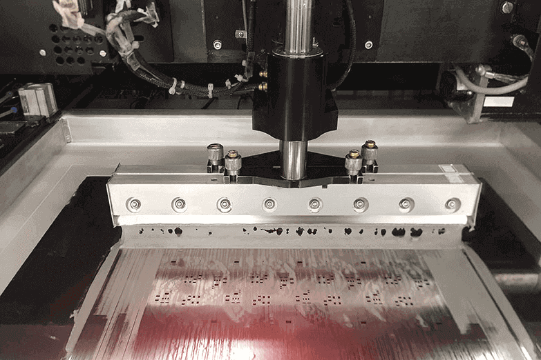
Solder mask is printed over the copper and opened only where a joint is required. The legend is printed on top of the mask, and then the exposed copper is finished, with a metal such as tin, silver, gold or an organic coating that keeps the surface solderable.
The choice of finish is a process decision as much as a performance one. It sets the shelf life of the bare board, the flatness of the pad after storage and the compatibility of the surface with the paste and the profile used at assembly.
Profiling, Inspection and Test
The panel is routed or scored into boards, and the edges are finished to the outline in the drawing. Tooling holes, breakaway tabs and any special profile are produced at the same time, because reworking an outline after routing damages the edge.
Inspection follows the process rather than the batch. Automated optical inspection checks the pattern, electrical test checks the nets, and a sample is cross sectioned to confirm the layer stackup and the plating thickness.
Registration and Tolerance Stack
Every step contributes error to the position of the finished features. The inner layer pattern, the lamination shift, the drill position and the outer layer image all add together, and the total is what a fabricator checks against the drawing.
A stack that is built from an odd number of layers, or one that places a thin core next to a heavy copper plane, is harder to press flat, which is why an unbalanced stackup is normally avoided.
Prepreg and Material Selection
The resin system in the prepreg determines the dielectric constant, the loss, the glass transition temperature and the ability of the board to survive assembly and service. A high speed design and a general purpose board may use the same copper but not the same material.
Material choice also sets the press cycle, because a resin that flows differently needs a different temperature and pressure profile. Changing the material late in a project therefore changes the process window and sometimes the stackup thickness as well.
What the Design Can Do to Help
A design that respects the process produces a board with fewer surprises. Symmetrical copper distribution, sensible annular rings, vias that are not stacked on top of one another, and a stackup that keeps the same dielectric on both sides of the centre all reduce the risk.
The multilayer design decisions made before release are what the fabricator has to work with. Where the drawing and the process disagree, the process wins, and the difference appears as a yield loss rather than as a conversation.
Plating and Copper Distribution
Plating thickness is not uniform across a panel. Copper is attracted to the edges and to areas that are electrically isolated, so a board with a large area of dense pattern next to a wide open area may plate differently in the two regions unless the fabricator adds thieving or adjusts the current.

That is why a design review asks about copper balance. A plane that covers eighty percent of one layer and twenty percent of the next changes the current density during plating, and the difference shows up later as an uneven surface or as a thickness reading that falls outside the drawing limit.
Electrical Test and Coupon Data
Every panel carries coupons from which the fabricator cuts samples for cross sectioning. The coupon shows the dielectric thickness, the copper weight and the plating in the hole, and it is the evidence that the panel met the drawing rather than a claim that it did.
Electrical test confirms that the nets are connected and that no two nets are shorted. It does not measure impedance unless the design specifies a coupon for that purpose, which is why a controlled impedance board should carry a test coupon and a stated tolerance for it.
Where the Process Sets the Design Rules
The minimum trace width, the minimum space, the smallest drill and the annular ring are process limits before they are design preferences. A rule that ignores them produces a board that the fabricator has to reject or to build at a loss of yield that appears in the price.
Reading the capability of the shop and writing the design to it is cheaper than learning the limits from a failed batch. The stackup rules and the drill table in the fabrication drawing are the two places where that conversation happens.
FAQ
How many layers does a typical multilayer PCB use? Four and six layers cover most products, with eight or more used when the routing density or the impedance requirements demand it.
Why is the finished thickness not just the sum of the sheets? Because the resin in the prepreg flows during lamination. The press cycle and the copper distribution both influence the final thickness.
What limits the smallest hole size? The aspect ratio of the drill to the board thickness, and the ability of the plating process to cover the wall of the hole reliably.