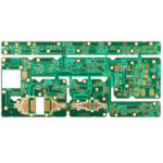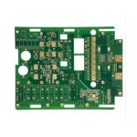
PCB Laminate Selection for Mixed Circuits
A product that contains a radio, a processor and a sensor front end on one board puts three different electrical requirements on the same laminate. Selecting the material is a compromise between the loss the radio can tolerate, the impedance the digital interfaces need and the cost the product can carry.
When One Board Carries Three Circuits
Radio sections are usually laid out as a separate area, sometimes on a small board of their own, because keeping the distributed parameters predictable matters more there than routing density. The digital section wants many layers and fine traces, and the analog section wants quiet references.
Placing them on one laminate forces the designer to decide which requirement dominates. A material chosen for the radio will also serve the rest of the board well, at a price, while a standard laminate chosen for the digital section will limit how far the radio design can be pushed.
Why FR-4 Is Often Still Right
A general purpose glass reinforced epoxy remains the correct answer for most products. Its dielectric constant is stable enough for controlled impedance over the temperature range a consumer product sees, its loss is acceptable below a few gigahertz, and it is available everywhere at a known price.
The material becomes the wrong answer when the loss budget, the phase stability or the thermal demand exceeds what it can deliver. That limit is a property of the specific grade rather than of the family, because the term FR-4 covers a wide range of resins and glass styles.
<img src="https://www.gopcba.com/wp-content/uploads/2024/09/PCB_Assembly_Process.webp" alt="Stackup samples of standard and high frequency laminates” />
Dielectric Constant and Trace Geometry
The dielectric constant sets the relationship between the trace width, the dielectric thickness and the characteristic impedance. A material with a lower constant allows a wider trace for the same impedance, or the same trace on a thinner dielectric.
The constant also varies with frequency and with the resin content of the glass, so the value quoted in a datasheet is a design value rather than a constant. A fabricator that changes the prepreg to achieve a thickness may change the impedance as well, which is why the stackup is verified rather than assumed.
Loss and the Frequency Where It Bites
Loss has two parts. The conductor loss depends on the copper, its roughness and the frequency, while the dielectric loss depends on the material and rises with frequency. At low frequency the copper dominates, and at high frequency the material does.
The crossover is the point at which a better laminate starts to pay. Below it, a low loss material buys very little, and above it the same material is the difference between a link that closes and one that does not.
Crosstalk and Spacing
Crosstalk is governed by the geometry as much as by the material. Two traces running in parallel with a thin dielectric between them and the plane couple strongly, and the coupling grows as the spacing falls and as the parallel run gets longer.
A lower dielectric constant reduces the coupling for the same geometry, but it is rarely the cheapest fix. Increasing the spacing, separating the aggressor and the victim with a grounded trace between them, or moving one of them to another layer addresses the same problem at the layout stage.
Termination and Impedance Continuity
Matching the driver to the line is what prevents reflections, and it only works if the impedance is continuous along the path. A change of layer, a connector, or a section routed on a different dielectric thickness is a discontinuity that a termination resistor cannot correct.
The value of the termination depends on the actual impedance, so a stackup that differs from the design assumption shifts the optimum. This is one more reason to have the fabricator confirm the impedance coupons before the layout is frozen.
Choosing a Material Class
Four classes cover most projects. Standard FR-4 suits general digital and low frequency analog work. A mid-loss grade with a better controlled constant serves interfaces up to a few gigahertz. A high frequency laminate with low loss and tight tolerance serves radio and microwave work, and a ceramic filled material serves applications where the constant itself has to be very stable.
Within each class there are grades, and the differences between them are usually in the control of the dielectric constant, the loss tangent and the glass transition temperature rather than in the headline number.
Mixing Materials on One Board
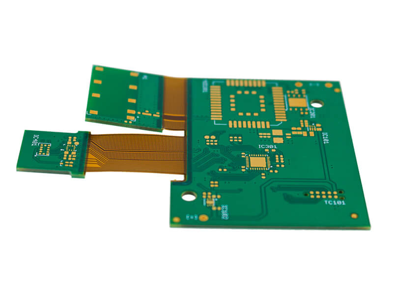
It is possible to build one board from two materials, using a low loss laminate for the radio layers and a standard one elsewhere. The construction is more difficult, because the two materials have different coefficients of expansion and different press requirements.
The benefit is cost, since only part of the stack uses the expensive material. The penalty is a longer qualification and a fabricator willing to run the construction, both of which should be established before the design depends on it.
Cost, Lead Time and Supply
A high frequency laminate can cost several times the price of standard FR-4 for the same panel area, and it may not be stocked in the thickness the stackup requires. Lead time grows with the specialty of the material and with the number of suppliers able to press it.
Availability is a genuine design constraint. A material that is available in one region and not another turns a manufacturing transfer into a redesign, so the choice should consider where the product will be built across its life.
What Belongs in the Drawing
The fabrication drawing should state the stackup, the dielectric thickness of each layer, the target impedance with its tolerance and the material class, not simply the trade name of a laminate. That information is what lets a fabricator propose an equivalent without changing the electrical result.
Impedance coupons belong in the same document, with the layer and the line geometry they represent. The layer stackup section of the drawing and the impedance table are the two places where the material decision becomes a manufacturing instruction, and both should be reviewed whenever the stackup changes.
Process Control and Verification
On a design of this kind, dielectric constant is the item that decides how the rest of the board is arranged. The process window is set by the narrowest step in the flow, so an improvement anywhere else shows up as margin rather than as yield until that step is addressed. A short note on the drawing about handling, storage or packaging is often worth more than an extra decimal place on a tolerance.
Process Control and Verification
On a design of this kind, dielectric constant is the item that decides how the rest of the board is arranged. The process window is set by the narrowest step in the flow, so an improvement anywhere else shows up as margin rather than as yield until that step is addressed. A short note on the drawing about handling, storage or packaging is often worth more than an extra decimal place on a tolerance.
Thermal and Mechanical Requirements
The material also decides how the board behaves under heat and load. A higher glass transition temperature keeps the laminate stiff and dimensionally stable during assembly, which matters for a thick board, a large panel or a component with a heavy thermal mass.
Expansion has to be matched to the assembly as well. A leadless ceramic device on a laminate that expands differently will stress its joints with every thermal cycle, and the material choice is part of the answer to that problem alongside the solder and the profile.
Qualification and Sample Builds
A material change is not proven by a datasheet. It is proven by building the board, measuring the impedance coupons, assembling a sample and running the thermal and environmental tests the product requires. That is the sequence that catches the differences a specification does not describe.
Before the change is released, the earlier stackup and its measurements should be kept for comparison. Being able to put the old and new results side by side is what turns a supplier proposal into a decision with evidence behind it.
FAQ
Can a radio and a processor share an FR-4 board? Yes, at moderate frequencies, provided the radio area is laid out with its own reference plane and the impedance is controlled across the whole path.
Does a lower dielectric constant always reduce crosstalk? It reduces coupling for a given geometry, but spacing and the presence of a reference plane usually matter more.
How is a material change managed? By specifying the electrical parameters rather than the trade name, and by verifying the impedance coupons. The routing consequences are covered under high frequency routing and the spacing rules under the 3W rule.