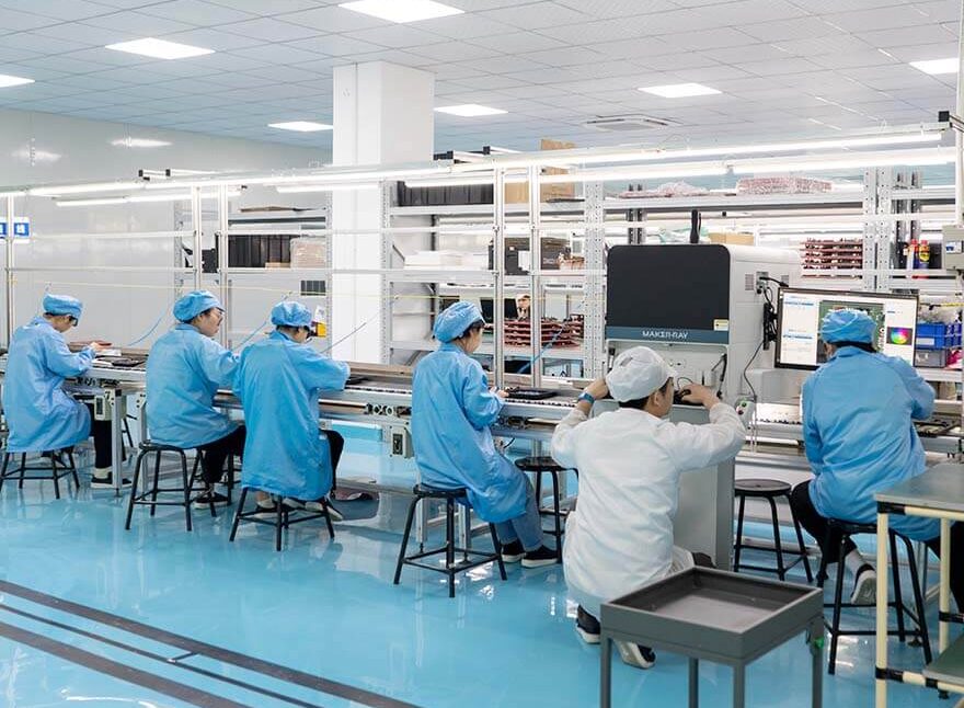
AI Vision Processor Board Design for 8K Camera Systems
A camera that records 8K video and runs neural network inference in the same device puts two heavy loads on one board. Designing around an ai vision processor means planning the high speed interfaces, the power delivery and the thermal path together rather than in sequence.
What the Processor Integrates
The class of device discussed here combines an image signal processor, a video encoder and a neural network accelerator on one die, together with a multi core application processor and a memory controller. Only the sensor, the memory and the power stage are external.
That integration is what makes a small camera possible. It also concentrates the design risk, because every high speed interface now terminates within a few millimetres of the others on a fine pitch package.
Camera Interfaces
Sensors connect over MIPI CSI lanes, and a modern device may support several independent inputs and more than a dozen total lanes. Each lane is a differential pair that has to be matched in length and referenced to a continuous plane.
Route each pair with the same length as its partners, keep the intra pair skew small and avoid vias wherever the pinout allows. Where a via cannot be avoided, place the corresponding ground vias beside it so that the return current has a short path.
Package Escape at Fine Pitch
A processor in a full grid array with half millimetre ball pitch cannot be escaped on a conventional through hole process. Escape routing needs fine lines, small laser drilled vias and often a buried or stacked via structure beneath the device.
Plan the fanout before the stackup is frozen. The number of rows that can be escaped on each layer decides the layer count, and it is far cheaper to add a layer at the start than to rework the escape after the design is complete.
Memory Interface
The processor is usually paired with lpddr memory on a wide bus. Data groups are routed together, length matched within the group and referenced to a plane that does not carry other switching current.
Because the bus runs at a high rate, its return path must be continuous from the package to the memory. A plane split under the bus is a common cause of a link that trains at a lower speed than the device supports.
Power Integrity
A high performance processor draws a current that changes within a few nanoseconds, so power integrity is decided by the loop between the die and the nearest capacitor. Every nanohenry in that path turns into a voltage excursion at the die.
Use a plane pair close to the device, place the smallest capacitors directly beneath the package on the far side, and keep the via pattern short and numerous. The bulk capacitance then only has to handle the slower envelope of the load.
Thermal Design
A device built on an advanced node can do a great deal of work for a few watts, but those watts still have to leave a small package. Thermal design starts with copper area and thermal vias under the die and ends with a defined contact to the mechanical structure.
In a sealed camera the case is the heat sink. Specify the flatness and the contact area of the interface, choose a gap filler with a defined thickness, and verify the junction temperature in the enclosure rather than on an open bench.
Storage and Boot
Video and model data are stored on managed flash or a card, and the boot image is held on the same medium or on a dedicated device. The interface speed of the boot medium decides how quickly the product is ready after power up.
A recovery path is worth the board area. A serial download mode or a second boot image allows a unit that fails during a firmware update to be recovered without being disassembled.
Security
Secure boot verifies the firmware before it is executed, and memory encryption protects the models and the recorded data. Both are usually built into the processor and depend on the board only for a small number of one time programmable bits and a trusted key source.
Close the debug interface in production. A camera that leaves the factory with an open JTAG port and an unprogrammed security fuse is an accessible device on any network it reaches.
Electromagnetic Behaviour
The camera interfaces, the memory bus and the switching supplies are the main sources of emission. Shielding the sensor and the processor with a grounded frame helps, provided the shield is bonded to ground at many points.
Filter the power input and the external connectors, and keep the connectors away from the sensitive analogue front end of the image sensor. Cable routing outside the product matters as much as the layout inside it.
Bring Up and Validation
Bring up on a first article in stages: power rails and sequencing, then the clock and the reset, then the debug port, then memory training and finally the sensor link. Logging each stage turns a silent failure into a known point.
Validation should include a long recording at the highest frame rate and a sustained inference load at the rated ambient. The combination of the two is what exposes a power or thermal margin that is thinner than the bench test suggested.
Choosing the Sensor Interface
Sensors with different resolutions and frame rates may share the same lane standard, so the interface design is driven by the fastest device in the product rather than the one fitted on the first build.
Where several sensors are used, the total lane count and the trace length from each connector decide how the pairs are grouped. Length matching rules for these nets are the same as those used for any matched length bus.
Mechanical and Optical Alignment
The image sensor has to sit at the focal plane and on the optical axis, so its position is defined by the lens mount rather than by the board. That makes the mounting holes and the sensor footprint a mechanical constraint on the layout.
Allow for the placement tolerance of both the sensor and the mount, and define the datum from the same features. Our notes on board outline and mounting cover the same class of decision.
Test and Production
A camera module is validated by the image it produces, so the production test has to include an optical measurement rather than an electrical one alone. A reference target and a defined illumination are part of the fixture.
The fine pitch package also needs inspection, and the checks used for X-ray solder inspection apply directly to the joints beneath the processor and the memory.
FAQ
How many layers does a board of this kind need? It depends on the escape and the memory bus, but boards with a fine pitch grid array processor and a wide memory bus commonly need eight to twelve layers with laser drilled vias.
Can the camera be built without a heat spreader? Sometimes, if the enclosure provides a flat surface close to the package and the power budget is small. A design that relies on air movement is a poor choice for a sealed outdoor product.
Why does the memory link train at a lower speed than expected? The usual causes are an interrupted reference plane, mismatched lengths within a byte group, or excessive crosstalk where the bus runs close to another high speed interface.