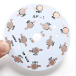
PCB Circuit Types Classification for Mixed Signal Layout
Before a mixed signal board can be laid out it has to be classified. Separating the circuit types on the drawing, and then deciding what interferes with what, is what turns a general set of layout rules into decisions for one board.
Classifying the Circuits
Analogue circuits include radio frequency stages, their supplies and control circuits, data converters and audio paths. All of them are sensitive to interference, and a few of them are sensitive to almost everything.
The most critical are the receive front end, the frequency generation circuits and the audio stages. These are the blocks that determine whether the product works at all in a crowded spectrum.
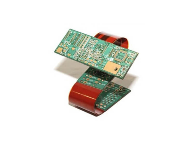
Identifying the Interference Sources
Digital circuits, high power radio stages and their antennas act as sources. Within them, the clock circuits, the switching supplies, the heavy current supply traces and the power amplifier are the ones that radiate most.
Classifying a block as a source does not mean it should be treated badly. It means its return currents and its edges have to be managed so that the energy stays close to where it was generated.
How the Interference Travels
Coupling happens through radiation between nearby circuits, through the supply and ground conductors, through the data converter that joins both domains and through the control signals that run alongside analogue circuits.
Radiation is the most visible in a layout review, but the supply and ground path is usually the more damaging. Both domains share one return structure, and everything that flows in it is seen by the sensitive circuits.
Placement Rules for Analogue Blocks
Analogue parts are placed in the analogue region of the board and digital parts in the digital region. The boundary is defined before placement begins, and it is a line on the floor plan rather than a line drawn afterwards.
Converters belong to neither group entirely. They are treated as analogue devices and placed in the analogue area, but their digital interfaces are arranged so that the digital side faces the digital region.
Shielding the Critical Blocks
Where the sensitivity justifies the cost, a metal shield can be placed over the receive front end, the frequency synthesiser and the power amplifier. The shield is part of the mechanical design as much as the layout.
Different circuits should have independent supply paths wherever the board area allows. Sharing a rail between a power amplifier and a receiver couples the largest signal on the board into the smallest one.
Supply and Ground Partitioning
Filter the supply as it enters the analogue region, and bring the digital and analogue supplies in from different directions so that their return currents do not overlap. A ferrite bead or a small resistor at the boundary is a common and effective measure.
Within one direction of flow, feed the large signal blocks first and the small signal blocks further along. The voltage drop and the noise generated upstream then appear at a point where they matter least.
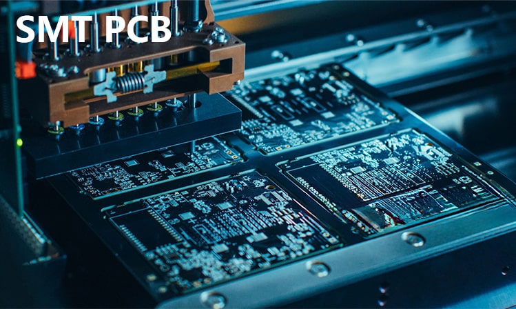
Trace Routing Between Domains
Where a digital signal has to cross into the analogue region, it should cross at a single defined point and be filtered there. A control line that wanders between the two regions couples them wherever it goes.
Keep the crossing perpendicular to the partition and never run a digital trace parallel to an analogue one. Parallel runs couple through the field between them, and the analogue circuit has far less tolerance for it than a digital one.
Grounding the Radio Stages
Radio devices need their ground pins connected locally to the reference plane of the radio signal. Where the layer beneath has been cleared, the connection has to reach the next plane down through a short via group.
Reserve space for those vias during placement. Adding them after the routing is complete means moving traces that were already tuned, which is a task with no good outcome.
Thermal and Power Considerations
Power stages and regulators dissipate heat, and the copper that carries it is also part of the circuit. Reserve the copper area needed for the thermal path at placement time rather than discovering the need later.
The supply trace to a power amplifier should be as short as the layout allows, both to reduce the voltage drop and to limit the loop area that radiates.
Reviewing the Classification
Review the floor plan against the classification before routing starts. Every block should be in the region that matches its type, and every crossing between regions should be deliberate.
Then check the return paths. A board that follows the placement rules but shares return conductors between the two domains will still perform badly, and the measures used to avoid that are covered in our notes on mixed signal layout and on ground and power planning.
Splitting the Board Into Regions
Draw the partition on the floor plan before placement and keep it visible while the parts are arranged. A region boundary that is defined early is respected, while one that is decided afterwards is a description of what was already done.
Where a board is too small for separate regions, the same discipline applies in miniature: analogue parts together at one end, digital parts at the other and converters on the boundary between them.
Signal Return Paths Between Regions
A signal that crosses between regions carries its return current with it. Where the two regions have different reference planes, the return has to be connected at the crossing point or the current will find an uncontrolled path.
Providing that connection deliberately is what makes a partitioned design work. Leaving it to chance is what makes a mixed signal board behave unpredictably in the field rather than on the bench.
Measuring the Result
Classification is only useful if it can be checked. Measure the noise floor of the analogue channel with the digital side idle, then with it running at full load, and compare the two results.
A difference between the two measurements is a coupling path, and its size tells you whether the layout measures are working. The same comparison is used in our notes on crosstalk.
Keeping the Rules Simple
A classification scheme with a dozen categories is not used. Four or five, understood by everyone on the team, are enough to drive the placement and the supply planning.
Write the scheme down with the floor plan, and review both at the same time. A rule that nobody can remember does not survive the first schedule pressure.
Documenting the Classification
Write the classification down with the floor plan, and keep the two together in the design file. A note that explains which blocks are sources and which are sensitive is what allows the layout to be reviewed by someone who did not draw it.
The note also survives the project. When the next revision adds a radio or a switching supply, the reason for the original arrangement is available rather than remembered.
Dealing With a Small Board
Where the product has no room for separate regions, the answer is to control the return path rather than the distance. A continuous reference plane with a defined join between the domains can outperform a physically separated layout.
The measures that make that work are the same as those used on a larger board: filter the supply at the boundary, cross the partition once and keep the return current under the signal that produced it.
FAQ
Should the analogue and digital grounds be separate planes? They can be separate regions joined at a single point, but a split that has no defined join is worse than one continuous reference with careful placement.
Is a shield always necessary over the radio stage? No. It is used where the receiver sensitivity or the emissions limit demands it, and the decision is made from a measurement rather than from habit.
How wide should the supply traces to the power amplifier be? Wide enough that the voltage drop and the temperature rise both stay inside the design target. The calculation is the same as for any current carrying trace.