Shielding Cans, Grounding and Board Level EMC
A shielding can is a metal box soldered over a circuit that would otherwise radiate or receive. It works by providing a conductive enclosure around the source, and its performance depends on how well that enclosure is completed: a can that is soldered at four corners and nowhere else is not the same shield as one that is stitched along its whole edge.
The design of the shield is therefore an electrical exercise with mechanical consequences. It affects the layout underneath it, the assembly process and the rework path, and it is usually decided late in the project when the first radiated emission measurement fails.
What a Shield Actually Does
An enclosure reflects and absorbs the field that reaches it, and it carries the currents induced on its surface back to the ground reference. The shielding effectiveness depends on the conductivity of the material, the frequency of interest and the completeness of the enclosure.
At the frequencies of most digital circuits, a thin metal can with a well connected perimeter is effective. At higher frequencies the thickness of the material matters as well, because the skin depth becomes comparable with the wall.
Ground Stitching and the Perimeter
The perimeter is where the shield works or fails. Every gap between the can and the ground plane is an opening, and the field escapes through it. Ground stitching the whole perimeter reduces the size of those openings and lowers the impedance of the return path.
The stitching vias should be spaced closely compared with the wavelength of the highest frequency of interest, which in practice means a spacing of a few millimetres for a fast digital circuit. The vias are placed on the board at the same pitch as the can’s clips or its solderable edge, and the pattern is part of the layout, not an afterthought. The reasoning about return paths is the same one discussed under EMI suppression.
Apertures and Necessary Openings
A shield always has openings: a hole for a connector, a slot for a display, a gap for a cable. Each is an aperture through which the field can pass, and its effect depends on its largest dimension rather than on its area.
A long narrow slot is a much better antenna than a round hole of the same area, which is why a connector cut out in the side of a can is often the dominant leak. Where an opening is unavoidable, it should be made as small as possible in its longest dimension and, where it is practical, divided into several shorter openings by adding material across it.
Cavity Resonance
A metal box over a ground plane forms a cavity, and a cavity has resonances at frequencies set by its dimensions. At a resonance the field inside builds up, and the shield can amplify the emission at that frequency rather than suppressing it.
The remedy is to change the geometry. Adding a post or a divider that connects the can to the ground plane in the middle of the cavity breaks it into two smaller ones with higher resonant frequencies, and often that is enough to move the resonance out of the band of interest.
Heat and Access Under the Can
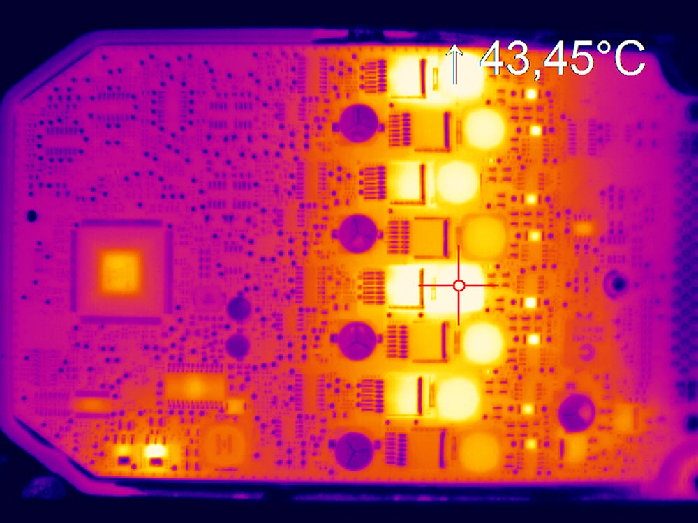
A shield traps heat as well as fields. A power device under a can needs a thermal path to the board, and the ambient temperature inside the enclosure will be higher than outside it. The thermal design has to account for the enclosure.
Access for rework is the other mechanical issue. A can that is soldered all around is difficult to remove without damaging the board and the components underneath, so the design should provide a way to inspect and repair what it covers. Where the circuit is expected to need adjustment, a removable lid or a two piece can is the practical choice, even though it costs slightly more shielding performance.
Material, Plating and Assembly
Shielding cans are usually made from a thin metal sheet, often a nickel silver or a tin plated steel, and they are supplied with a solderable finish. The finish has to be compatible with the paste and with the reflow profile, and it has to survive the storage between manufacture and assembly.
A frame and lid construction allows the frame to be soldered during reflow and the lid to be fitted afterwards, which keeps the soldering step simple and makes the cavity accessible. The frame has to be flat enough to sit on the board without gaps, and its width determines how much board area the shield consumes.
Verification of the Shield
The measurement is the radiated emission test, and it should be made with the shield fitted and with it removed to confirm that it is doing something. A shield that makes no measurable difference is either not connected properly or is not needed.
Near field probing on the bench can show where the field is coming from before the shield is designed, which is more efficient than shielding blindly. That investigation is the same one that precedes any fabrication decision about the board, and it is best done while the layout can still change.
Process Control and Verification
On a design of this kind, radiated emission is the item that decides how the rest of the board is arranged. Running a first article through the same checks as the production panel confirms that the two agree, and that comparison is the cheapest form of process control available at prototype stage. Keeping a sample from the panel turns a dispute into a measurement, because the same coupon can be re-examined by both parties without rebuilding the batch.
Reviewing the design before the data is released is cheaper than correcting it after the panel is in the tank, because every step downstream inherits the decision made at the front end. Documenting the assumption is part of the design work, and a short note on the drawing prevents a question that would otherwise arrive a day later and cost a day of schedule.
Related reading: our fabrication notes, board quality and design release notes cover the same ground.
Process Control and Verification
On a design of this kind, radiated emission is the item that decides how the rest of the board is arranged. Running a first article through the same checks as the production panel confirms that the two agree, and that comparison is the cheapest form of process control available at prototype stage. Keeping a sample from the panel turns a dispute into a measurement, because the same coupon can be re-examined by both parties without rebuilding the batch.
FAQ
Does a shield have to be soldered all around? It has to be connected with a small pitch along the perimeter. Soldering the full edge is one way; a row of clips and vias is another.
Can a shield be added after the layout is finished? It can, but the stitching vias and the keep out area have to exist on the board. Adding both late usually means a re-spin.
Does a shield affect the thermal design? Yes. It raises the ambient temperature inside the enclosure and it blocks convection, so the thermal path has to be designed with the can in place.