Aluminium Substrate PCB Design for LED Strip Boards
Lighting boards are the clearest case where the board is part of the thermal design. An aluminium substrate carries the light emitting devices, spreads their heat and often forms part of the fixture itself.
Why LED Strips Use a Metal Board
A light emitting diode converts only part of its input into light, and the remainder becomes heat in a very small package. That heat has to leave through the solder joint and the board beneath it.
Glass fibre laminate conducts heat poorly, so a conventional board would need a large copper area and an external heat sink. A metal core board spreads the heat laterally and lets the fixture act as the heat sink.
Construction of an Aluminium Substrate
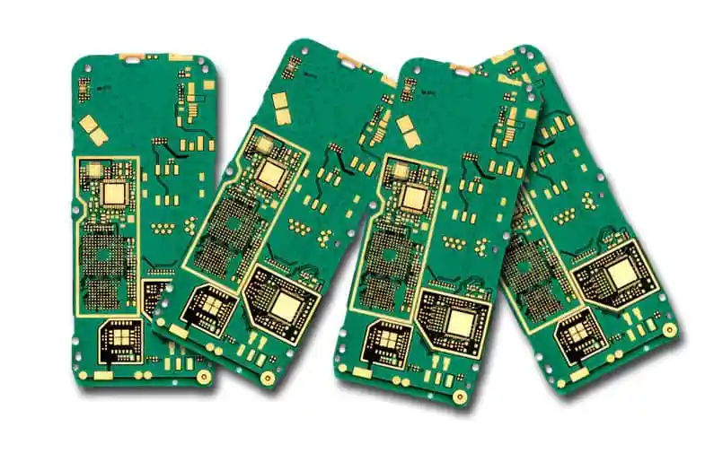
The board has three layers: a metal base, an insulating layer and the copper circuit. The base is usually aluminium because it is light, inexpensive and easy to machine and bend.
A double sided version adds a second insulation layer and a second circuit on the back. More than two circuit layers on a metal base is rare, because the insulation layers would have to be laminated repeatedly.
The Insulation Layer
The insulation layer provides the dielectric strength between the circuit and the metal base, and it also sets the thermal resistance of the board. Its thickness is a compromise between breakdown voltage and heat transfer.
A thicker layer withstands more voltage and conducts less heat. Where the board is used on mains derived circuits the thickness follows the safety requirement, and that requirement is what limits the thermal performance.
Thermal Path
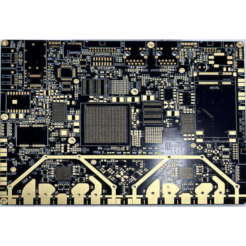
Heat flows from the device into the copper pad, through the insulation layer into the aluminium, and then spreads to the fixture. Each interface adds a thermal resistance, and the largest is usually the insulation layer.
Thermal vias cannot be used in the usual way, because they would have to pass through the metal base. Copper area around the device and a good contact between the board and the fixture are the practical levers.
Copper Thickness and Current
Lighting boards often carry a substantial current along a narrow strip, so the copper weight matters as much as the thermal design. One or two ounce copper is common, and heavier foil is used where the run is long.
The current calculation is the same as on any board, but the ambient is higher because the fixture is warm. Our notes on trace width describe the calculation used here.
Strip Layout and Voltage Drop
A long strip fed from one end has a voltage that falls along its length, so the far end is dimmer than the near end. Feeding from both ends halves the drop, and a wider conductor reduces it further.
The drop is calculated from the resistance of the conductor, not from the current alone. On a strip of several metres the copper resistance becomes the dominant design constraint.
Series and Parallel Segments
Devices are arranged in series strings with a current limiting element, or in parallel groups with a driver. The arrangement decides the voltage the fixture needs and the effect of a single device failing.
Where constant voltage is used, each segment carries its own resistor or regulator. Where constant current is used, the segments are driven by a supply that regulates the current, which removes the variation between strings.
Connectors and Solder Joints
Connections on a strip are usually made by a soldered wire, a pair of pads or a board to board connector. Each of them is a mechanical joint on a board that will be bent and installed.
The joint area needs strain relief. A wire that is soldered to a narrow strip and then pulled will lift the copper, and the failure appears as an intermittent segment rather than as a broken joint.
Bending and Mechanical Limits
Aluminium boards can be bent and formed, but the insulation layer is brittle compared with the metal. Bending radius, the direction of the bend relative to the circuit and the position of the copper all matter.
Keep the circuit away from the bend line where possible, and keep the bend radius generous. A crack in the insulation layer may not fail immediately, which makes it a difficult fault to find later.
Surface Finish
The finish has to be solderable and it has to survive the environment. An organic finish is adequate for a fixture that is assembled immediately, while a metallic finish is chosen where the board is stored or exposed.
Where the strip is used outdoors, the finish and the solder mask are part of the environmental protection. Conformal coating is often applied over the assembled board as well.
Mounting and Assembly
The metal base can be screwed directly to a fixture, which is one of the advantages of the construction. Where the base is part of an electrical path, the mounting has to be insulated.
Assembly usually involves surface mount devices on one side only, which simplifies the stencil and the reflow process. The thermal mass of the metal base means the reflow profile has to be measured on the real board.
Failure Modes to Design Against
The common failures are a cracked insulation layer under a bent board, a lifted pad at a wire joint and a device that runs too hot because the thermal path was interrupted. Each has a design measure.
Measure the temperature of the device in the real fixture rather than on an open bench. A board that is comfortable in the open can exceed the device rating once it is inside a sealed luminaire.
Design Checklist
Confirm the voltage and current per segment, the copper weight and the width of the feed, the insulation thickness required by the safety standard and the thermal contact with the fixture.
Then check the mechanical design: bend radius, joint strain relief, mounting insulation and clearances. The general rules are collected in our notes on manufacturability and on design and fabrication.
Driving the Strip
A constant voltage supply is simple and needs only a resistor per segment, but the current changes with temperature and the brightness follows. A constant current driver holds the current and removes that variation.
The choice affects the board, because a driver adds components and often a switching stage. Where the driver switches, its loop area and its placement belong to the same design rules as any other converter layout.
Optical and Mechanical Integration
The board positions the emitters relative to the diffuser, the reflector and the lens. Small errors in that relationship show as uneven illumination rather than as an electrical fault.
Dimension the mounting holes from the optical reference rather than from the board edge, and keep the copper clear of the areas that are compressed by the fixture. The tolerances that matter here are mechanical and are stated on the same drawing as the circuit.
FAQ
Can a normal glass fibre board be used for an LED strip? It can, with enough copper and a heat sink. Where the power is high or the space is tight, the metal core board transfers the heat with far less area.
Why does the far end of a long strip look dimmer? Because the copper resistance drops the voltage along the strip. Feeding from both ends or widening the conductor reduces the difference.
Is a thicker insulation layer better? It is better for voltage withstand and worse for heat transfer. The thickness is chosen to meet the safety requirement and no more.