SMT Adhesive For Wave Soldering And Dispensing
On a mixed technology assembly, the surface mount parts on the underside have to survive a wave of molten solder while the through hole joints on the top side are being made. A small chip component has nothing to hold it in place once the adhesive strength of the flux is gone, and the turbulence of the wave will carry it away unless it is bonded to the board. A dot of adhesive placed between the pads solves that problem, and it introduces a set of process requirements of its own.
This article explains what the adhesive has to do, how the materials and the dispensing methods differ, how the dot is sized and placed, and how the result is verified.
What The Adhesive Has To Do
The bond has to hold the component through several steps: the placement itself, the handling between stations, the cure, the reflow of the opposite side, and the thermal shock and mechanical force of the wave. It also has to remain electrically insulating, chemically compatible with the flux, and stable at the wave temperature, because an adhesive that softens, outgases, or decomposes will release the part or contaminate the solder.
The strength that matters during placement is the green strength, which is the tack that holds the part before the material is cured. A component that is dislodged by a nozzle or by a board transfer is a defect that has nothing to do with the final bond, and it is the reason a fast curing adhesive or an ultraviolet cure step is often used immediately after placement.
The order of the operations is often what decides whether the process works. Where a board is built with the small parts on the underside, the usual sequence is to print and place the bottom side, dispense and cure the adhesive, turn the board over, and then print, place, and reflow the top side before wave soldering the through hole joints. Each of those steps imposes a thermal load on the adhesive, and a material that was selected for its strength at the wave temperature may still soften during the top side reflow if its cure was incomplete.
Materials And Cure Options
An epoxy gives the strongest and most thermally stable bond, and it is the usual choice where the part is small and the environment is demanding. An acrylic cures quickly under ultraviolet light, which suits high volume production, while a polyurethane offers flexibility at a lower strength. Within each family the properties that matter are the viscosity, the thixotropy, the pot life, and the cure schedule.
The cure can be thermal, ultraviolet, or a combination of the two. A thermal cure is thorough and works in shadowed areas, but it takes minutes and it heats the whole assembly; an ultraviolet cure takes seconds but only reaches what the light can see, so a combined cure is used where speed matters and the dot is not fully exposed. The cure schedule is part of the material specification rather than a line setting, because an under cured dot will fail in the wave and an over cured one may become brittle.
Dispensing And The Dot Profile
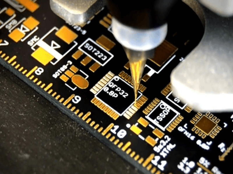
The dot can be dispensed as a liquid, transferred by a pin, or printed through a stencil. Dispensing is the most flexible, since the volume and the position can be programmed per component, and it is the method used where the board carries a mix of part sizes. The volume is the critical parameter: too little and the part is released by the wave, too much and the adhesive squeezes out from under the body onto the pad, where it blocks the solder joint.
The position is as important as the volume. The dot is placed between the pads, on the laminate or on the solder mask, so that the bond is to the board rather than to a solderable surface. A large component may need two dots, one at each end, and the height of the cured dot has to leave the component resting on its pads rather than floating above them. A dot that is too tall lifts the part and produces an open joint, which is the failure that looks like a placement problem and is actually a dispensing problem.
Design And Process Considerations
The footprint has to allow room for the adhesive as well as for the solder. The gap between the two pads of a chip component is the usual location, and a solder mask dam in that gap keeps the solder from bridging while providing a surface for the dot. Where the gap is small, the dot has to be smaller, which reduces the bond strength, so a very small component on a fine pitch footprint may need a different strategy such as a stencil printed adhesive pattern.
The process sequence matters as well. The adhesive is normally dispensed after placement and cured before the board is turned over, and the cure temperature has to be compatible with the components that are already mounted and with the solder paste that has already been printed. Where the assembly is reflowed after the adhesive is cured, the material has to survive that excursion without softening enough to release the parts, and it has to survive the wave that follows.
Defects And Verification
The defects are predictable. A missing dot lets the component float away in the wave, and it is usually caused by a clogged nozzle or an empty syringe. An excessive dot lifts the part or spreads onto a pad, which produces an open joint or a poor fillet. A dot that is displaced sideways bonds to one pad instead of the laminate, which weakens the hold and contaminates the joint. An incompletely cured dot allows the part to move during the wave, which produces a partial or a bridged joint.
Verification uses three checks. The dot volume is confirmed by dispensing onto a glass slide or a test board and measuring the profile, which is a setup check rather than a production check. The bond strength is measured with a push off test on a sample, in which a defined force is applied to the side of a mounted component and the result is compared with a limit. The wave result is confirmed by inspecting the assembly after soldering for missing, shifted, or poorly soldered parts, and by checking that no adhesive has reached a solderable surface. The dispensing processes and materials are described under potting and dispensing adhesives, the placement behaviour under component shift during reflow, and the footprint rules under manufacturable design guidelines.
FAQ
Where is the adhesive dot placed? Between the pads of the component, on the laminate or on the solder mask, so that it bonds to the board and not to a solderable surface. Adhesive on a pad prevents wetting and produces an open joint.
Why is green strength important? Because the part has to stay in place between placement and cure. A material with a low tack allows the component to be displaced by handling or by the next process step.
Can the adhesive be cured by ultraviolet light alone? Only where the light reaches the whole dot. A shadowed area stays uncured, so a combined ultraviolet and thermal cure is used where the geometry is not fully exposed.