Impedance Test Coupon Design And Verification
A controlled impedance requirement is a promise about a transmission line, and the only way to know whether the promise was kept is to measure a line that was built with the same process as the product. That is what an impedance test coupon is: a set of transmission lines placed in the waste area of the panel, built in the same stackup, the same plating and the same etch as the boards beside them, and measured after fabrication.
This article explains what a coupon contains, where it is placed, how it is measured, what the numbers mean, and what a designer should put on the fabrication drawing to make the measurement useful.
What The Coupon Is For
The impedance of a trace depends on its width, on the thickness and dielectric constant of the material above and below it, and on the thickness of the copper. Every one of those quantities varies in production. Etching changes the width, pressing changes the dielectric thickness, and the plating adds copper to the outer layers unevenly across the panel. The coupon measures the result of all of them together, which is why it is more informative than a stackup calculation.
The coupon also serves as a record. It is measured on the finished panel and sometimes retained as a physical sample, so a question about a delivered batch can be answered from data that was taken at the time rather than from a calculation performed afterwards. Where a customer requires a certificate of compliance per lot, the coupon measurement is normally the evidence behind it.
Where The Coupon Goes
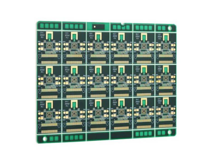
The coupon belongs in the panel, not on a separate test panel. Copper thickness, etch rate and dielectric thickness all vary with position, so a coupon built on its own panel tells you about that panel and not about the boards. Placing it in the rail or in the waste area between boards puts it in the same chemical and thermal environment as the product.
Position within the panel matters as well. A coupon at the centre and a coupon at the edge will not read the same, because plating is thicker near the bus bar and the etch is more aggressive where the copper density is low. For a board with a tight tolerance, coupons are placed at more than one position, and the spread between them is part of the process capability rather than an anomaly.
What The Coupon Contains
A useful coupon contains one line for each type of transmission line that the design uses, at the width that the design uses. A microstrip on the outer layer, a stripline between two inner layers and a differential pair are different structures and need different lines. Each line is given a length that is long enough to be measured accurately, typically 50 to 150 millimetres, and ends in a launch pattern that a probe can contact without adding an unknown inductance.
The coupon may also carry the test structures that the shop needs anyway, such as a resistance and a continuity pattern for the electrical test, a solderability coupon for the finish, and a thermal stress coupon for the plating. Combining them keeps the amount of panel area used for test under control, which matters because that area is board area that cannot be sold.
How The Lines Are Measured
Time domain reflectometry sends a fast step along the line and reads the reflection that comes back from any change in impedance. The instrument reports the impedance as a function of time, which the operator converts to distance along the line. The technique is fast and gives a clear picture, but the launch, the probe and the length of the line all contribute, so a short line measured with a long probe will read low.
A vector network analyser measures the line in the frequency domain and reports the characteristic impedance, the loss and the delay. It is more accurate and more informative than a single number from a reflectometer, and it is the method used when the requirement includes the loss of the channel as well as its impedance. Both methods should be used with a calibration standard that is traceable, and the result reported together with the temperature at which it was taken.
Reading The Result And Controlling The Process
The measured impedance of a single line is a sample, not the population. What the shop controls is the mean and the spread of the coupons over a period, and the limit on the drawing is normally written as a nominal value with a tolerance that covers both. A line that measures inside the tolerance at one position and outside it at another is telling you about the panel, not about the design.
When the reading is out, the direction of the error points to the cause. Too high an impedance usually means the trace is narrow, the dielectric is thick or the dielectric constant is low; too low means the opposite. The structure of the line and the way its geometry is chosen are described under microstrip and stripline routing and layer stackup from one to eight layers.
What Goes On The Drawing
The fabrication drawing should name the layers, the line width and the target impedance for each structure, the measurement method, the coupon length and the frequency band over which the requirement applies. It should also state whether the coupon is measured on every panel or on a sample, and what happens to the boards if the coupon is outside the limit.
Where the requirement is only written as a single number without a method, the shop will choose a method, and two shops will report different figures for the same design. Writing the method and the tolerance removes the ambiguity before the order is placed, which is the same discipline that applies to the rest of the fabrication package, described under PCB design and fabrication.
Mistakes In Coupon Design
The most common fault in coupon design is a line whose width does not match the product. A coupon that is drawn at a convenient round number rather than at the width the signal layer actually uses will measure something, and that measurement will be irrelevant. The second fault is a launch pattern that is too small or too close to the panel edge for the probe to land on it reliably, which produces a reading that varies each time the operator touches the line.
The third fault is a line that is shorter than the rise time of the instrument can resolve, so the reflection from the far end arrives before the near end has settled and the reported impedance is a blend of the line and its terminations. A coupon design that takes these three points into account costs nothing extra, while one that ignores them produces data that has to be discounted and a requirement that cannot be verified.
FAQ
Can the impedance of a trace on the finished board be measured directly? It can, with a probe and a careful launch, but the pad and the probe add discontinuities that are larger than the tolerance on a short line. The coupon exists because it can be measured without those additions.
How often should the coupon be measured? On every panel for a tight requirement, or on a defined sample where the process has been shown to be capable. The frequency is a process control decision and should be stated on the drawing.
Does the coupon guarantee the board? No. It shows that the process produced the intended geometry at the coupon position. Boards elsewhere on the panel and boards from other panels are covered by the same process, and the coupon is evidence about the process rather than about each individual trace.