EMI Shielding Can Design And Via Stitching
A shielding can is a metal cover soldered or clipped over a circuit to stop radio frequency energy leaving it, and sometimes to stop energy entering it. The can itself is simple; the design problem is the ground connection that makes it work, the cavity that it creates, and the openings that have to be left for the signals and the ventilation. A can that is not grounded properly is worse than no can at all, because it can turn a broadband problem into a narrow band one or move the emission to a frequency that was previously clean.
This article explains how the shield behaves, how the ground connection is arranged, how the cavity is controlled, and how the result is verified.
What The Shield Does
A conductive enclosure attenuates the field that passes through it by reflecting and absorbing it. The attenuation depends on the conductivity and the thickness of the metal, on the frequency, and above all on the integrity of the enclosure. At the frequencies where a shield is used, the metal is almost never the limiting factor; the leakage is through the seams, the openings and the imperfect ground connection around the perimeter.
A shield also affects the circuit it covers. It changes the impedance of any trace that is coupled to it, it forms a capacitance to the ground plane beneath, and on a board that uses the can as part of a resonator it changes the tuning. Those effects are not defects, but they are consequences of the shield that have to be accounted for in the layouts that are placed under it.

The Ground Connection
The can has to be connected to the reference plane all the way around its perimeter, and the connections have to be close enough together to attenuate the frequencies of interest. The spacing between adjacent stitching vias is set by the shortest wavelength that the shield must contain: a common rule is to keep the spacing below one twentieth of that wavelength, which for a 1 gigahertz component means about 15 millimetres, and for 6 gigahertz about 2.5 millimetres.
The vias are placed along a fence that follows the outline of the can, connected to ground on every layer they pass through. Gaps in the fence become slots that radiate, and the largest gap sets the performance of the whole shield. Where a signal crosses the fence, the trace has to cross with a continuous return path, and the general rules for that are described under ground routing and power trace planning.
Cavity Resonance
The space between the can and the ground plane is a cavity, and a cavity resonates at frequencies set by its dimensions and by the dielectric constant of the material inside. At resonance the field inside the cavity is intensified, and the shield becomes a radiator instead of a suppressor. The lowest resonance of a rectangular cavity is set by its longest dimension, so a long, narrow can resonates at a lower frequency than a square one of the same area.
The remedies are geometric. The can is divided into smaller compartments by internal walls or by additional rows of stitching vias, which raises the resonant frequency of each compartment above the band of interest. Absorbing material is sometimes placed inside the can, and a matte finish on the inside surface reduces the reflections that build the resonance. Raising the can further from the board lowers the resonant frequency, so the height is chosen with the same consideration.
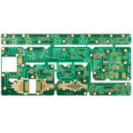
<img src="https://www.gopcba.com/wp-content/uploads/2024/09/Multilayer-impedance-PCB.jpg" alt="Via fence around the outline of a shield land” />
Openings, Seams And Apertures
An opening radiates in proportion to its longest dimension, not to its area. A long thin slot for a connector or a flex is a far better antenna than a group of small round holes with the same total area, so a design that needs ventilation should use a pattern of small holes rather than one large cut out. The same reasoning applies to the seam where two halves of a shield meet: a continuous weld or a conductive gasket is required, and a seam that is only spot welded leaks between the spots.
The shield has to be attached to the board as well, and the attachment is part of the electrical design. A can that is soldered along a continuous land has the best performance, while a clip on can relies on spring fingers that make contact at intervals. The spacing of those fingers is the stitching distance of the shield, and it has to be specified rather than left to the clip supplier. The wider set of measures for keeping emissions inside the product is described under EMI suppression design principles and under EMI reduction through stackup and layout.
Mechanical And Assembly Considerations
A shield is a mechanical part as well as an electrical one. It has to survive the assembly process, the reflow temperature if it is soldered, the handling of the finished product and any flexing of the board. A large unsupported can over a thin board will bellows when the board flexes and its feet will lift, which opens the ground connection at exactly the moment when the product is being stressed.
The land that the can is soldered to is a copper area on the surface, and it needs to be wide enough for the solder fillet and for the placement tolerance of the can. It also has to be kept clear of other components and of the mask, and on a board that is assembled on both sides the can is normally placed last or first depending on which side is reflowed second, because a can over a component prevents the nozzle of a rework tool reaching it.
Verification
Verification is a measurement of the field rather than of the circuit. A near field probe moved over the board with and without the can shows how much the shield attenuates, and a scan of the aperture and the seams shows where the leakage is. The measurement is normally done in an anechoic chamber for the final product and with a probe on the bench for development.
The other check is the effect on the circuit. The impedance of the traces under the can, the tuning of any filter and the frequency of any oscillator are all compared before and after the shield is fitted, because a shield that changes the function of the circuit has solved one problem by creating another. The stackup and layout measures that reduce the need for shielding in the first place are described under EMI reduction through stackup and layout.
FAQ
How far apart should stitching vias be? Below one twentieth of the wavelength of the highest frequency that has to be contained, which is about 15 millimetres at 1 gigahertz and 2.5 millimetres at 6 gigahertz.
Does the can have to be soldered? Not always, but a clip on can is only as good as the contact between its fingers and the land, and the finger spacing then becomes the stitching distance of the shield.
Can a plastic housing with conductive paint replace a metal can? It can, for a product where the shield is fitted to the enclosure rather than to the board, provided the paint is continuous and the joint between the halves of the housing is conductive along its whole length.