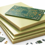
Impedance Test Coupon: Preparation, Placement and Process Control
A controlled impedance board is only as good as the evidence that its traces have the impedance the design intended. That evidence comes from a coupon built on the same panel, with the same stackup and the same etch process, whose traces are measured and compared with the target.
This article covers where the coupon goes, how the trace is measured, how the stackup and the etch affect the result, and how the measurement is reported.
Why A Coupon Instead Of The Product
An impedance test coupon is used because the product traces cannot be measured non-destructively. A time domain reflectometry measurement requires access to both ends of a uniform trace, and a product trace runs between components, changes layer, passes under a shield or ends at a pad that is covered by an assembled part. The coupon provides a trace with the same width, the same dielectric separation and the same copper thickness, but with probe access at both ends.
The coupon is placed in the panel border, where it can be cut out and measured without touching a product board, or in a location inside the panel where the panel would otherwise be waste. What matters is that it sees the same process: the same lamination cycle, the same plating, the same etch. A coupon that is placed in a quiet corner of the panel, where the copper density is lower than on the product, may have a different etch result from the product itself, which is the main weakness of the method. The stackup the coupon represents is defined under layer stackup from one to eight layers.
How The Measurement Works
Time domain reflectometry sends a fast pulse along the trace and records the reflection that returns from any change in impedance. The trace itself is a uniform transmission line, so its impedance appears as a flat plateau in the reflected waveform, and the height of that plateau is converted into an impedance value. A rise or a dip in the plateau indicates a local change, such as a connector, a via or a change of width.
The measurement depends on the rise time of the pulse and on the length of the trace. A slow pulse averages over a longer distance and hides short variations; a fast pulse resolves more but is more affected by the probe transition and by the launch into the trace. The trace has to be long enough that the plateau is fully formed before the reflection from the far end returns, which is why a coupon trace is usually several centimetres long. The probe pads themselves contribute a discontinuity, so the launch geometry is defined by the coupon design and used consistently.

Stackup And Etch Tolerance
The impedance of a trace is set by its width, the thickness of the dielectric beneath it, the thickness of the copper and the dielectric constant of the material. The designer chooses the width for a nominal stackup, and the fabricator then has to build a board whose actual values fall within the tolerance. Two of those variables move more than the others: the dielectric thickness, which depends on the prepreg and the press cycle, and the etch, which determines the finished trace width.
Etch is the variable that causes the most trouble, because it depends on the copper density around the trace. A trace in a dense area etches more slowly than an isolated one, and a coupon placed in a sparse region will measure a wider trace and a lower impedance than the same trace on the product. Where a tight impedance tolerance is required, the coupon is laid out with the same copper density as the product area it represents, and the fabricator adjusts the artwork according to the coupon result. The basic transmission line behaviour that underlies all of this is described under PCB routing with microstrip and stripline.
What The Result Tells You
A coupon result that is inside the tolerance confirms that the stackup and the etch produced the intended geometry. A result that is outside the tolerance does not by itself say which variable moved. If the impedance is low, the trace may be too wide, which points at the etch, or the dielectric may be too thin, which points at the lamination. Distinguishing them requires the geometry to be measured as well, by sectioning the coupon and measuring the trace width and the dielectric thickness.
That is why a coupon result is normally reported together with the measured geometry. The impedance number is the acceptance criterion, and the geometry is the diagnostic. A board shop that reports only the impedance leaves its customer unable to tell whether the process is drifting or the measurement is at fault, and it cannot correct a trend before the parts leave tolerance. The tolerance stack that includes the geometry is part of the wider design discipline in the advantages of multilayer construction at high speed.

Reporting And Sampling
The report should state the coupon location on the panel, the trace type (surface microstrip, embedded microstrip or stripline), the nominal width and dielectric, the target impedance and its tolerance, and the measured value with the instrument’s rise time. Without the rise time the number is not comparable with a measurement taken elsewhere, and without the coupon location it cannot be related to the product.
Sampling is normally per panel lot rather than per panel, with a coupon measured from each lot and the coupon retained. Where the process is stable, some shops measure every panel because the measurement is quick and the consequence of an out of tolerance shipment is severe. Where the product is used at a high data rate, the coupon may also carry a differential pair, and the measurement then includes the differential impedance and the skew between the two lines of the pair. The routing practices that keep that skew small are described under routing high frequency traces and data buses.
Common Measurement Mistakes
The most common mistake is measuring a trace that is too short, so that the reflection from the far end arrives before the plateau has settled and the reading is pulled towards the value of the terminating structure. The second is leaving the far end open or shorted rather than terminated, which produces a large reflection that masks the trace. The third is a probe launch that is not the same as the one used for the reference, so the discontinuity at the launch is counted as part of the trace.
The fourth is comparing results between instruments without comparing rise times. Two instruments with different rise times will report different values for the same trace, because the slower one averages over more of the trace and over the launch discontinuity. Fixing the instrument and the probe for all measurements, and recording them in the report, removes this source of argument and makes the coupon a control rather than a source of debate.
FAQ
Can the product trace be measured directly? Sometimes, where both ends are accessible on a test coupon that duplicates the product geometry. For a finished assembly it is not possible, because the trace is covered and loaded by components.
How tight should the impedance tolerance be? It comes from the interface specification the product is built to, and it is normally between five and ten percent. A tighter tolerance raises the fabricator’s cost because it reduces the process window for etch and lamination.
Does the coupon guarantee the product impedance? It guarantees it only where the coupon sees the same copper density and the same process as the product. A coupon in a sparse area of the panel can pass while a dense product area is outside tolerance.