UV Laser Depaneling For Assemblies
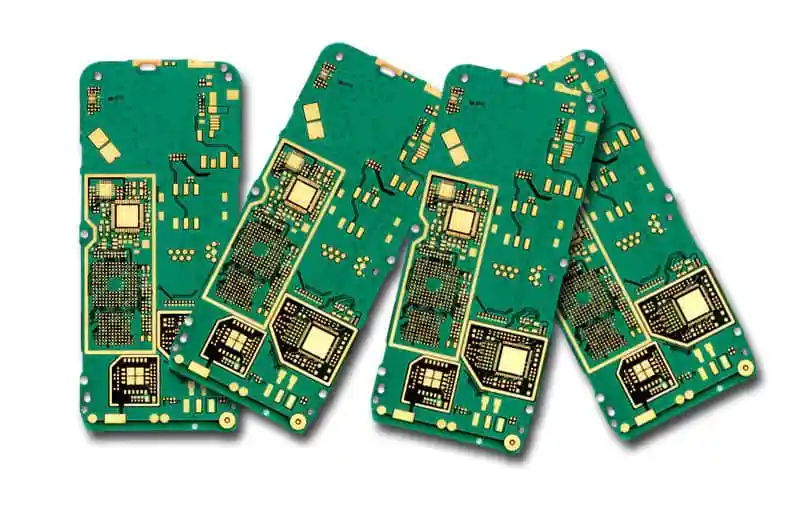
Laser depaneling separates boards from their panel with a focused beam instead of a router bit. It applies no mechanical force to the assembly, it can follow any outline including a curve or an internal cut-out, and it leaves no dust in the sense of a cloud of particles, because the material is vaporised and extracted rather than cut into chips.
This article covers how the process works, how the heat affected zone is controlled, what the cut edge looks like, and where it is the right choice.
Why A Laser For Depaneling
The advantages over routing are the absence of mechanical force and the freedom of the cut path. A router pushes the board as it cuts, which loads the solder joints near the cut; a laser puts no load on the assembly at all, which matters on a board carrying ceramic capacitors or a large ball grid array near the edge. The path freedom means a board with a curved outline or a cut-out can be separated without a special fixture, and the cut can be arranged to avoid a component that a router would have had to clear.
The laser also cuts a narrower path than a router bit, which saves material and allows boards to be packed more closely on the panel. That reduction in the panel gap can be significant where the board is small and the routing allowance dominated the layout. The general treatment of edges and cuts is described under PCB slot and edge routing rules.
The UV Wavelength And Its Effect
The wavelength of the laser determines how it removes material. An ultraviolet laser at a wavelength in the hundreds of nanometres has photons with enough energy to break polymer bonds directly, a process called cold ablation. A longer wavelength, in the infrared, is absorbed as heat, which melts and vaporises the material. The difference in the cut is visible: a cold ablation cut has a narrow heat affected zone and a clean edge, while a thermal cut leaves a charred band.
The choice of wavelength also affects the focal spot size, because a shorter wavelength can be focused to a smaller point. A smaller spot cuts a narrower kerf and removes less material, which raises the cutting speed for a given energy. That is the reason the ultraviolet laser has become the standard for depaneling, in the same way that it is used for drilling microvias in a high density board.
Heat Affected Zone And Carbonisation
Even a cold ablation process leaves a heat affected zone, a thin band beside the cut where the material has been heated enough to change. In a laminate this band shows as a discoloured region, and at the extreme it becomes carbonised: the resin has decomposed into a conductive char. A carbonised edge is more than a cosmetic problem, because the char is conductive and it can bridge two conductors that the cut passes between, and because it can absorb moisture and degrade the insulation resistance.
The zone is controlled by the energy per pulse, the overlap between pulses, the number of passes and the assist gas. A high energy per pulse with a large overlap removes material quickly and leaves a wider zone; a lower energy with more passes gives a cleaner edge at a lower speed. The assist gas removes the vapour and the debris, and it also cools the cut, so its flow and direction are part of the process rather than an accessory. Cleaning the board after cutting removes the surface debris, but it does not remove a zone that is inside the laminate.
Cut Edge Quality
The edge left by a laser is a slightly tapered wall with a fine texture, and the taper is a consequence of the beam being focused to a point so that the energy density falls away from the focal plane. On a thin board the taper is small; on a thick board it can be visible, and the edge is then no longer perpendicular to the surface. Where the edge has to fit a mechanical feature, the taper has to be included in the tolerance.
The edge also has a slight discolouration, from the heat affected zone, which varies with the material. Some laminates cut cleanly with little visible effect, while a heavily filled or a very glass rich material shows more. Where the edge is exposed in the finished product, the appearance may need to be agreed with the customer, and the requirement should be stated as a limit on the discolouration rather than as an expectation. The mechanical constraints at the edge belong with the general design rules under board outline and mounting design.

Throughput And Programming
The cutting speed depends on the material, the thickness and the required edge quality, and it is slower than a router for a simple straight cut. The value comes from the absence of a fixture and from the freedom of the path, not from raw speed. The programming is a path for the beam, generated from the board outline, and it is quick to change, which makes the process attractive for a product with many variants that share a board size.
The panel has to be held during cutting, and the holding method matters because the parts must not move once they are separated. A vacuum table or a fixture with pins is used, and the cut path is programmed so that each board stays attached until its cut is complete. Where the panel is held by the border and the boards are cut free, the last few cuts release a board that is no longer supported, and the sequence has to be planned so that a released board cannot move into the beam path.
Where It Fits In The Process
Laser depaneling is normally done after assembly and after the electrical test, in the same position in the flow as a router or a v-score break. It is chosen where the mechanical force of the alternative is unacceptable, where the outline is not a straight line, or where the panel density is high enough that the saved gap matters. It is not chosen on cost alone, because the machine is more expensive per board than a router for a simple outline.
The design measures that make it work are to keep a path for the beam, to avoid placing a component or a conductor where the cut must pass, and to allow for the kerf width and the taper in the edge tolerance. Those are simple constraints, and stating them at the design stage is what allows the process to be selected later without a redesign. The complete set of fabrication driven constraints is collected under design guidelines for manufacturability.
FAQ
Does laser depaneling damage the board electrically? It does not, provided the cut does not reach a conductor and the heat affected zone is controlled. A carbonised edge is the exception, because the char is conductive and can bridge a gap that the cut passes through.
Is it faster than routing? For a simple straight cut, no. For a complex outline that would need a special fixture, or for a panel where the gap saved by the narrower cut allows more boards, it can be the faster and cheaper option overall.
What is the cut edge tolerance? It depends on the material, the thickness and the optics, and typically it is a little wider than a routed edge. Where the edge has a mechanical function, the tolerance should be agreed with the supplier rather than assumed.