Selective Soldering: Practical Checks for Production
Selective soldering applies solder to individual through hole joints with a small nozzle, which lets a board carry parts that cannot survive a wave. The process is local, and every parameter in it is set for one joint rather than for a whole panel.
How the Nozzle Works
The nozzle holds a small wave or a bath of molten solder and the board is brought to it. The diameter is chosen from the pad size and the pin pitch, and it has to fit between neighbouring features.
A nozzle that is too large bridges and one that is too small does not reach the barrel. Our through hole notes describe the alternative process.
Flux and Its Activation
The flux is applied before the joint reaches the solder, and it has to be dry and activated by the preheat. A flux that is still wet boils in the nozzle and leaves voids.
The flux volume is set per joint rather than per board. Our flux notes describe the control that also applies here.
Preheat and Dwell
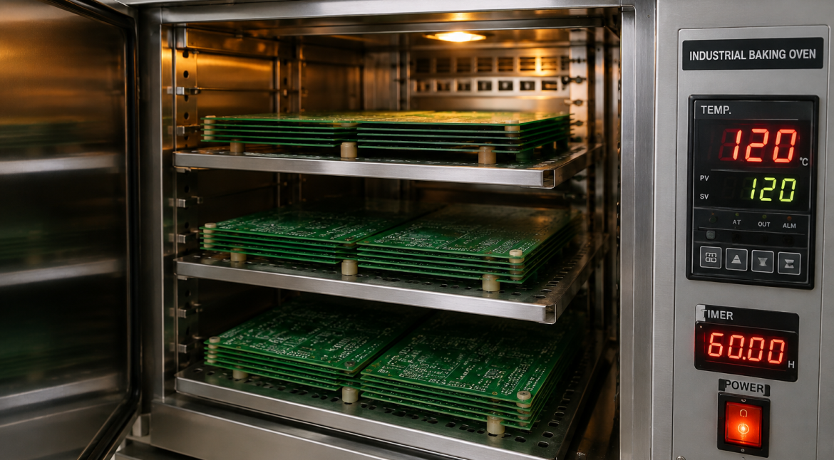
Preheat brings the joint close to the soldering temperature so that the nozzle does not have to supply all the energy. Dwell is then the time the joint spends in contact with the solder.
Both are recorded per program, because a change in either moves the fill. Our thermal measurement notes describe the recording.
Thermal Profile of a Local Process
The board around the joint is not heated to soldering temperature, so heat is drawn away into the surrounding copper. A joint connected to a plane therefore needs a longer dwell than an isolated one.
The difference between a thermal and a non thermal pad should be written into the program. Our thermal design notes describe the copper that causes it.
Fill and Fillet Criteria
The acceptance is a vertical fill percentage in the barrel and a visible fillet on the top and bottom side. The figure should be stated rather than left to judgement.
Our joint criteria notes describe the acceptance that applies.
Records and Changeover
The program number, the nozzle size, the flux type and the profile belong to the setup record. Where a board carries several connector types, each has its own program and its own record.
Our floor control notes describe how the records are held.
Verification
The verification is a first article joint sectioned to show the vertical fill, a profile recorded at the joint, and a bridging check on the same board.
Our first pass yield notes describe how the records are used.
Additional Considerations for This Build
Practical attention to flux activation pays for itself here, because it decides whether the finished board behaves as the drawing intended. Where the requirement is not stated on the fabrication drawing or in the assembly notes, the shop has to assume a default, and that default is rarely the value the design was simulated with. Stating flux activation explicitly, together with the tolerance that applies, removes the assumption and keeps the result predictable from batch to batch.
Deliberate attention to dwell time pays for itself here, because it decides whether the finished board behaves as the drawing intended. Where the requirement is not stated on the fabrication drawing or in the assembly notes, the shop has to assume a default, and that default is rarely the value the design was simulated with. Stating dwell time explicitly, together with the tolerance that applies, removes the assumption and keeps the result predictable from batch to batch.
Process Control and Verification
On a design of this kind, nozzle is the item that decides how the rest of the board is arranged. The measurements that matter are the repeatable ones: conductor width and spacing, annular ring, finished hole size, plating thickness and surface finish are all verifiable on a coupon that travels with the panel. Running a first article through the same checks as the production panel confirms that the two agree, and that comparison is the cheapest form of process control available at prototype stage.
Keeping a sample from the panel turns a dispute into a measurement, because the same coupon can be re-examined by both parties without rebuilding the batch. Reviewing the design before the data is released is cheaper than correcting it after the panel is in the tank, because every step downstream inherits the decision made at the front end.
Documenting the assumption is part of the design work, and a short note on the drawing prevents a question that would otherwise arrive a day later and cost a day of schedule. The process window is set by the narrowest step in the flow, so an improvement anywhere else shows up as margin rather than as yield until that step is addressed.
A short note on the drawing about handling, storage or packaging is often worth more than an extra decimal place on a tolerance. Where a value sits close to a process limit, the drawing should say so, since the shop can then open the process window rather than working to a nominal figure that carries no tolerance.
A stack-up that is drawn rather than described removes most of the ambiguity from a quotation, and it lets the fabricator price the board against the dielectric and copper weights that will actually be used.
Process Control and Verification
On a design of this kind, nozzle is the item that decides how the rest of the board is arranged. The measurements that matter are the repeatable ones: conductor width and spacing, annular ring, finished hole size, plating thickness and surface finish are all verifiable on a coupon that travels with the panel. Running a first article through the same checks as the production panel confirms that the two agree, and that comparison is the cheapest form of process control available at prototype stage.
Keeping a sample from the panel turns a dispute into a measurement, because the same coupon can be re-examined by both parties without rebuilding the batch. Reviewing the design before the data is released is cheaper than correcting it after the panel is in the tank, because every step downstream inherits the decision made at the front end.
Process Control and Verification
On a design of this kind, nozzle is the item that decides how the rest of the board is arranged. The measurements that matter are the repeatable ones: conductor width and spacing, annular ring, finished hole size, plating thickness and surface finish are all verifiable on a coupon that travels with the panel. Running a first article through the same checks as the production panel confirms that the two agree, and that comparison is the cheapest form of process control available at prototype stage.
A first article check confirms that the process and the drawing agree on the points listed above, and that the coupon data supports the values used in the design.
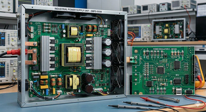
Where a measurement falls outside the expected window, the sample is retained so that the cause can be established before the balance of the batch is released.
FAQ
Can selective soldering handle a fine pitch connector? It is limited by the nozzle diameter, which has to fit between adjacent pins. Below that limit the process cannot reach the joint without bridging.
Is nitrogen needed? It reduces dross and improves wetting, and it helps most where the dwell is short and the joint is small.
What does gopcb provide for selective soldering? We provide a nozzle size chosen against the pad and the pitch, a flux volume set per joint, preheat and dwell recorded per program, a separate program for thermal and non thermal pads, and a first article sectioned to confirm the vertical fill.