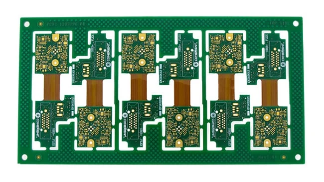
Wave Soldering: Setup and Defects
What the Wave Does
Wave soldering passes the board over a standing wave of molten solder, so that every exposed joint is soldered in a single pass. It is fast, it suits through-hole assemblies and mixed boards with the surface mount side already reflowed, and its quality depends on a small number of parameters that interact with each other. The wave is a thermal process and a fluid process at the same time: the board has to be hot enough for the solder to wet, and the flow has to reach every joint and drain away cleanly afterwards.
Flux Application
Flux removes the oxide from the copper and the solder so that the alloy can wet, and it has to be applied in the right quantity and in the right place. Too little and the joints oxidise before the wave arrives; too much and the residue becomes a cleaning problem, and on a dense board the excess can migrate under components. The methods are spray, foam and wave fluxing, with spray giving the most control and foam the least. The flux also has to be matched to the process: a no-clean chemistry is chosen where the board will not be washed, and a water-soluble one where it will, and the preheat has to activate the flux without consuming it before the wave.
Preheat
Preheat brings the board to a temperature at which the flux is active and the thermal shock of the wave is reduced. It also begins to dry the board and to drive off the volatile part of the flux. Typical top-side temperatures before the wave are in the region of 90 to 120 C depending on the flux, and the temperature should be uniform across the board, since a board that is hot on one side and cold on the other produces joints that behave differently. On a thick board or a board with heavy copper, the preheat has to be longer, because the thermal mass takes more energy to bring up.
The Wave and Contact
The wave itself is a flow of solder that contacts the underside of the board. The parameters are the wave height, which sets the contact area, and the nozzle shape, which sets the flow pattern. A chip wave or a turbulent wave ahead of the main wave helps the solder reach the joints in dense areas. The contact time is the ratio of the solder contact length to the conveyor speed, and it has to be long enough for the joint to reach soldering temperature and for the barrel to fill. A wave height that is too low leaves joints untouched; too high and the solder floods the top side.
Conveyor Speed and Angle
The conveyor speed sets the contact time and the cooling rate, and the conveyor angle sets the contact length and how the solder drains. A steeper angle increases the contact length but also changes how the solder separates from the board, which affects icicle formation and bridging. The parameters are set by the machine and the board, and a change to one usually requires a change to the others, which is why a wave setup is documented as a set of values rather than as a single speed.

Common Defects
Bridging between adjacent pads is usually caused by too much flux, by a wave that is too turbulent, or by pads that are too close for the drainage. Icicles and webbing come from a board or a wave that is moving while the solder is still liquid, or from a solder temperature that is too low. Shadows, where a joint receives no solder, are caused by a tall component blocking the flow or by a pad that is hidden behind a body, and they are a layout problem as much as a process one. Solder balls on the surface come from flux spatter or from a splash. Cold joints, in a wave process, usually mean the joint never received the wave rather than that the wave was too cold.
Design Rules for Wave Soldering
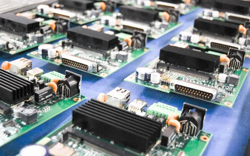
Keep components on the solder side out of the wave path, and avoid tall parts that shadow joints behind them. Orient the pads so that the solder drains away from the board rather than being trapped, which usually means running the pad’s long axis parallel to the conveyor direction where the machine allows a choice. Keep the spacing between pads large enough for the solder to separate, and use a thermal relief on any pad connected to a heavy plane so that the joint reaches temperature. Where a board has fine-pitch parts that the wave would bridge, they belong on the reflow side instead.
Pallets and Selective Alternatives
Many wave processes run the board in a pallet, which protects the surface mount side, supports thin boards and masks the areas that must not be soldered. The pallet openings have to match the joints and the mask has to be positioned so that it does not shield a joint from the preheat. Where only a few joints need through-hole soldering, selective soldering is usually the better answer, since it applies heat locally and avoids running the whole board through a wave.
Wave Soldering and Lead-Free Alloys
The transition to lead-free alloys changed the wave process more than the reflow process, because the wave has to deliver a large amount of heat to a board that is passing over it in a few seconds, and the lead-free alloys melt warmer and wet differently. The practical consequences are a higher solder pot temperature, a longer contact time, more aggressive flux, and greater dross formation on the surface of the pot, which can be dragged onto the board if the wave is not kept clean. The flux has to be more active to wet the copper in the shorter time available, which makes the residue more corrosive and makes cleaning more important where the product requires it. The design consequences are subtle but real: a pad that drained cleanly with a eutectic alloy may hold a small amount of solder at its edge with a lead-free one, and a spacing that was adequate before may now bridge.
FAQ
What does the wave do? It passes the board over a standing wave of molten solder so that all the exposed through-hole joints are soldered in one pass.
What is the most important parameter? The contact time, which is set by the wave contact length and the conveyor speed, and which has to be long enough to fill the barrel.
Why do shadows appear? Because a tall component blocks the flow to the joint behind it, which is a layout as well as a process issue.
How is bridging fixed? Reduce the flux volume, calm the wave, increase the pad spacing and check the drainage rather than only the profile.
Is wave soldering suitable for fine pitch? No. Fine-pitch parts belong on the reflow side, with the wave used for the through-hole joints only.
Conclusion
Wave soldering is a thermal and fluid process, so the flux, the preheat, the wave and the conveyor are one system, and the defects it produces point to one of them. Set the contact time from the barrel fill, keep the drainage in mind in the pad layout, and use selective soldering where only a few joints need through-hole work. Through-hole assembly sits alongside SMT PCB assembly, the resulting joints are checked through PCBA testing, and the pad geometry that governs drainage is part of PCB design and layout. Mixed assemblies are normally proven through prototype PCB assembly in 2026.