Copper Thickness Verification: X-Ray and Microsection
Copper thickness is one of the few characteristics of a printed board that is specified numerically on every drawing and verified on every order. It sets the current carrying capacity of a trace, the impedance of a controlled line, the thermal performance of a via and the mechanical strength of a barrel. Three methods dominate the shop floor: X-ray fluorescence, microsection and the coulometric test, and each of them answers a slightly different question about the same panel. Choosing between them is a matter of matching the method to the question being asked rather than of picking the most expensive instrument in the shop.
Why Copper Thickness Has to Be Verified
A drawing usually states a base foil weight and a finished plating thickness, and the two combine to give the copper the designer modelled. If the finished value is low the trace overheats under load and the via barrel cracks during thermal cycling, and if it is high the impedance falls and fine line etching becomes difficult because the etchant has to remove more metal. A heavy deposit also changes the aspect ratio of a fine line, which shifts the impedance of a controlled trace in the opposite direction to the one the designer intended.
Because the tolerance is normally a percentage rather than a fixed allowance, the verification method matters as much as the target. Two methods that disagree by ten percent will pass or fail the same panel depending on which one is used, so the method has to be agreed with the customer and stated on the inspection report.
X-Ray Fluorescence in Practice
X-ray fluorescence is the fastest method and the only one that is genuinely non destructive. A beam of X-rays excites the copper atoms and the detector counts the returning photons to estimate the mass per unit area, which the instrument converts into a thickness. A reading takes seconds, so many points can be sampled across a panel. That speed is what makes the method so useful for process control, because the spread across a panel can be mapped in a few minutes instead of in a few hours.
The method has limits. It measures only the area the beam covers, so it says nothing about the barrel of a hole, and the reading depends on the density and composition of the layer. A tin plated surface measured through the coating, or a copper layer with an unusual grain structure, gives a misleading number unless the instrument is calibrated for that exact stack. Calibration foils of a similar thickness and density to the expected layer should be used, and a measurement that falls near a calibration boundary should be confirmed by another method.

Microsection Preparation
Microsection is destructive, slow and the reference method against which the others are judged. A coupon is cut, mounted in resin, ground and polished until the feature of interest is exposed, and the copper is then measured under a microscope against a calibrated scale or with image analysis software.
Preparation quality decides the result. A section that is rounded at the edge, or one where the copper has been smeared by aggressive grinding, measures thin or thick depending on the direction of the error. The polishing routine has to be fixed, the operator trained, and each section examined for preparation damage before the numbers are released. The measurement itself should be taken at several points around the barrel and the barrel wall, because the thinnest point is the one that will fail the specification.
Coulometric and Other Methods
The coulometric test dissolves a small area of copper in a controlled cell and measures the charge needed to remove it, which gives the thickness directly from Faraday’s law. It is accurate and it can be aimed at a specific feature, but it is destructive and it needs a flat surface of known area. It is often used to settle a dispute, because the result comes directly from the amount of metal removed rather than from a calibration curve.
Other approaches include the eddy current probe, which is quick but sensitive to the material underneath, and weight loss on a test coupon, which gives an average over a known area. The weight loss method is slow and only usable on a coupon, but it is simple enough that it makes a good independent check on the instrument readings. Our plating thickness guide describes how these methods are combined in a production control plan.
Measuring on a Coupon
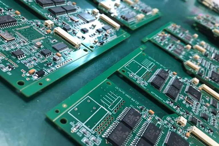
Most shops verify copper thickness on a coupon that travels with the production panel, because the coupon can be sectioned or dissolved without sacrificing product. The coupon has to be plated in the same current field as the product, which means it should be positioned deliberately rather than tucked into an unused corner. The coupon should also be plated on the same panel side and in the same orientation as the critical product features.
A coupon that sits at the panel edge, where the current density is highest, will always read higher than the product and give false confidence. Our test coupon guide explains how coupons are laid out and evaluated for the properties an order requires.
Through Hole and Barrel Copper
The barrel of a plated through hole is where copper thickness is hardest to control and where a failure is most expensive. Plating solution has to reach the middle of a deep hole, and the current density at the centre of the barrel is lower than at the surface, so the deposit is naturally thinner there. A high aspect ratio hole makes the problem worse, because the solution exchange inside the barrel becomes the limiting factor rather than the current density.
Specifications usually call for a minimum at the mid point of the barrel rather than an average, and the measurement has to come from a section rather than an inference. Our hole copper guide explains how aspect ratio, agitation and current waveform affect the distribution inside the hole.
Variation Across a Panel
Even a well run plating line produces a gradient. Current density is higher at the edges and around isolated features, and it is lower in the centre of a large panel and in dense areas. A single measurement therefore tells you about one point and almost nothing about the panel as a whole.
The useful practice is to sample a fixed pattern of points, record them separately and track the spread rather than only the average. A panel that passes on average and fails in the middle of a dense area is a real risk, and only a defined sampling pattern will find it before the customer does. The pattern should stay the same from lot to lot, because a pattern that changes cannot be compared with the historical record.
Interpreting Out of Specification Results
When a result falls outside the limit, the first question is whether the measurement or the process is at fault. Re-measuring the same section with a second method, or sectioning a second coupon, quickly separates an instrument problem from a genuine deposition problem. Verifying the instrument against a standard of known thickness takes a few minutes and answers the same question without consuming another coupon.
If the process is at fault, the likely causes are the current density, the plating time, the bath chemistry, the agitation or the panel loading. The plating log should narrow that down, because all of those variables are recorded on a line that is under control. A deviation that cannot be explained by the log usually means the log itself is incomplete, which is a finding worth acting on in its own right. Our quality documentation describes how such results are classified at gopcb.
Process Control Points
The control plan should state the method, the sampling points, the frequency and the acceptance limits for each copper layer, and it should distinguish between the foil, the plated deposit and the finished surface. Mixing those three together is a common source of argument with a customer. The report should quote the method alongside the number, so that a comparison with a supplier or a customer measurement is meaningful.
Instruments need calibration standards that bracket the expected thickness, and those standards should be traceable and re-verified on a schedule. With the method fixed and the data plotted over time, an excursion appears as a trend rather than as a surprise at final inspection. Copper thickness is therefore best managed as a measured trend across the panel and across time, rather than as a pass or fail decision on a single point.
FAQ
Which method is most accurate for copper thickness? Microsection is the reference method, but its accuracy depends on preparation quality. X-ray fluorescence is faster and non destructive, and the coulometric test is precise on a flat coupon. The method should be agreed with the customer rather than chosen by the shop.
Can X-ray fluorescence measure copper inside a hole? No. The beam only sees the surface it is aimed at, so barrel copper has to be measured on a polished section. This is the most common misunderstanding about the technique.
How many points should be measured on a panel? A fixed pattern covering the centre, the edges and the dense areas gives far more information than a single reading, and the trend across that pattern is more useful than the average value alone.