Depanelization Stress Control in PCB Assembly
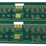
Separating a board from its panel is the last mechanical operation before test and enclosure, and it is also where a surprising share of latent damage is created. The cut itself looks clean, but the force that produces it travels through the laminate and into every solder joint attached to it. Depanelization stress is therefore a reliability variable, not just a mechanical one, and controlling it is cheaper than screening for the failures it causes.
Why Depaneling Is a Reliability Step
Bending strain damages brittle components long before it breaks them. A ceramic capacitor that flexes by a few hundred microstrain can develop a crack that opens only after thermal cycling in the field, and a ball grid array can see a solder joint separate over a period of months. Both defects pass the functional test that follows depaneling.
Because the damage is invisible at the time, the operation has to be controlled by its inputs rather than its outputs. That means knowing how much strain the process applies and keeping it below the threshold the components can tolerate, which is a measurable quantity rather than a matter of operator care.
Measuring Depanelization Stress
A strain gauge bonded to the board surface near a critical component converts deflection into a number in microstrain. The gauge is placed on the side opposite the component, oriented along the direction of maximum bending, and connected to a recorder that captures the transient during the cut. Peak values above roughly 500 microstrain are considered risky for ceramic chip components.
Measurements are worth taking when a process is first set up, when a board changes shape, and whenever a new failure mode appears. The data converts a vague worry into a specification: a limit, a measured value, and a clear decision about whether the operation is acceptable as it stands.
Routing Parameters That Reduce Strain
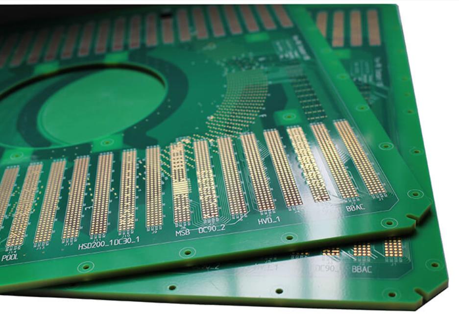
A router bit removes material with a rotating cutter, and the force it applies depends on feed rate, spindle speed, bit geometry and depth of cut. A dull bit or one with the wrong flute design pushes rather than cuts, and the resulting deflection appears as strain at the nearest tab. Bit diameter also sets how much material has to be removed before the panel releases.
The strongest single control is support. A board fully supported under the cut cannot deflect, so the strain path is closed. Where the panel is held only at its edges, every cut is a lever, and the geometry of the tabs decides how much leverage the operator or the machine can apply. Tab design and router parameters therefore have to be chosen together.
V-Score Separation by Hand
Scored panels are usually broken by hand or in a simple press. Hand breaking is fast and requires no tooling, but it is uncontrolled: the operator applies a bending moment until the web fails, and the magnitude depends on where the hands are placed and how the board is gripped. Snapping a large panel over a table edge is the classic way to create flex cracks.
A press with a blade that follows the score line is far more consistent because the load is applied along a line rather than at a point, and the board is supported on both sides of the break. Where hand breaking must be used, the panel should be gripped close to the score, supported near the break, and the movement should be a quick controlled snap rather than a slow bend.
Laser and Punch Methods
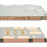
Laser depaneling removes material by ablation, so it applies essentially no mechanical force and produces very low strain. The trade is speed and cost, and a heat affected zone at the cut edge that has to be considered for the material and for any coating. For boards densely populated near the outline it is often the only method that meets the strain limit.
Punching and die cutting are fast and cheap at high volume, but they apply a shearing load across the whole outline at once. The tooling cost is significant and the method suits simple shapes in thin material. Where it is used, the die has to be designed so that the board is fully supported and the shear is applied cleanly.

Fixture and Support Design
A depaneling fixture should locate the panel by its rails or tooling holes, support the board directly under the cut line, and hold it so that the only movement possible is the one the process intends. Foam or elastomer pads spread the reaction load and stop the board from ringing after the cut.
The fixture also decides how the finished board is handled. A nest that keeps the board flat until the operator picks it up prevents the common accident where a partially separated board is lifted by one corner. Handling after the cut is part of the same strain budget, not a separate subject.
Component Distance Rules
The further a component sits from the break line, the less bending it experiences, and the relationship is not linear: strain falls quickly with distance because the bending moment decreases towards the supported region. Keeping brittle parts at least the thickness of the board away from any score or routed edge is a workable rule, and more where the panel is large.
Orientation matters too. A chip component whose long axis is perpendicular to the score line experiences the full bending curvature, while one aligned along it sees much less. Rotating a row of components is free at layout time and can remove an entire failure mode, as the experience collected in our note on flex cracking in ceramic capacitors shows.
Verification and Documentation
Verification means measuring rather than assuming. A strain measurement on the first build, a cross section of a sample joint after depaneling, and a record of the router bit life and feed settings together show whether the process is under control. Panel design and the tab geometry that interacts with it are described in our article on breakaway tab design.
Documentation should also cover what happens when the process drifts. Bit wear, fixture slack and operator variation are all normal, and the records that show a rising strain trend allow the tooling to be replaced before defects reach the field. Board flatness after depaneling is worth checking as well, and the methods in our note on PCB warpage control apply directly.
FAQ
What strain limit should be used? Around 500 microstrain is a common ceiling for boards carrying ceramic chip components, with lower limits for the largest case sizes. The right value depends on the components and should be confirmed against the supplier specification.
Is manual breaking ever acceptable? Yes on boards without brittle components and with a controlled technique. Where ceramic capacitors or large ball grid arrays are present, a press or a router is the safer choice.
Does laser depaneling remove all stress? It removes the mechanical load almost entirely, but it introduces a heat affected zone. The two effects have to be weighed for the material and the coating in use.