Impedance Coupon Verification for Controlled Boards
Impedance coupon verification is the step that proves a controlled impedance stackup is actually being built the way the drawing describes. The board may look correct, the layer count may match and the drill data may be right, yet the trace width, dielectric thickness or copper foil that sets the characteristic impedance can drift with no visible symptom at all. A coupon placed on the production panel and measured with time domain reflectometry converts those invisible variables into a number that can be compared against a limit.
Why a Coupon Rather Than a Board
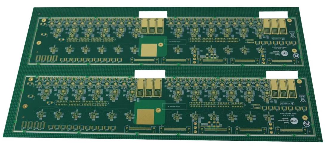
A production board is the wrong test article for impedance. Its traces are short, loaded with pads and vias, and routed where the layout needed them rather than where a measurement is convenient. A coupon avoids all of that: it is a dedicated structure with a known length, a defined reference plane and a launch footprint that makes the measurement repeatable. Because the coupon is fabricated on the same panel, with the same materials and the same process steps, it is a fair proxy for the product without being the product, and it can be measured in seconds rather than minutes.
The coupon also carries the process history. If a lot is etched slightly differently, laminated at a different pressure or plated to a different thickness, the change appears on the coupon first. Placing several coupons across the panel, in different positions, exposes within-panel variation that a single measurement would miss entirely, and that variation is what most often takes a stackup out of tolerance on one side of the panel while the other side passes.
Coupon Design and Stackup Match
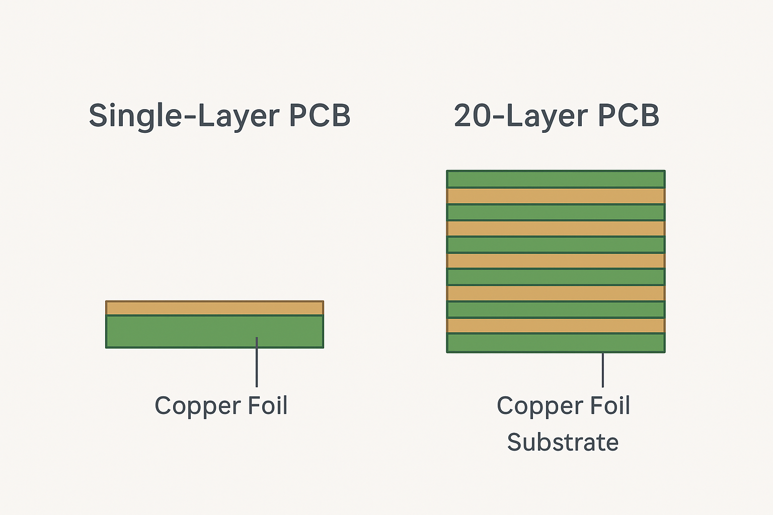
The coupon must match the product’s construction: the same dielectric material and thickness, the same copper weight and the same soldermask loading on the structures being measured. A coupon that omits the mask, or that uses a different reference plane spacing, produces a number that is internally consistent and externally wrong. The coupon drawing should therefore be released alongside the fabrication drawing and revised with it, so that a stackup change cannot happen without the test structure changing at the same time.
Coupon geometry also determines what can be measured. Single-ended lines, differential pairs, microstrip and stripline structures each need their own coupon features if the product uses them. Where the coupon must stay small for panel efficiency, the design usually keeps one differential pair, one single-ended line and a short length of the same line for loss measurement, with the launch structures placed at a defined pitch so that probing is repeatable between operators and between shifts.
Time Domain Reflectometry Basics
Time domain reflectometry sends a fast edge down the line and records the reflection that returns. The time between the launch and the reflection, and the shape of the reflected waveform, give the impedance profile of the trace. Instruments report impedance versus distance, so the operator can see whether the value is uniform along the line or whether a via, a connector or a mask opening introduces a discontinuity. The launch must be de-embedded, otherwise the connector dominates the result and the trace itself is never really measured.
Practical accuracy depends on the probe or connector, the reference plane, the calibration and the resolution of the instrument. A rough calibration throws the whole curve off by several ohms, which is enough to convert a passing lot into a failing one, or the reverse. Most programmes therefore fix the instrument, the cable, the probe and the calibration standard, and treat any change to that chain as a change to the measurement system that requires requalification before results are trusted.
Setting Tolerance Limits
Tolerance should come from the design, not from the process. A serial interface or a high-speed channel has an impedance target with an acceptable range derived from the signalling standard and from simulation, and the coupon limit is that range tightened slightly to leave room for measurement uncertainty. Deriving the limit from what the process happens to produce is the opposite of verification, because it quietly accepts whatever the shop can achieve today as the requirement.
Limits should also be expressed per structure and per position. A differential pair measured at one end of the panel may pass while the same structure at the other end fails, and averaging the two hides the problem rather than reporting it. Recording the worst case per structure, together with the fabrication tolerances that the shop has agreed to, gives a result that supports both the acceptance decision and the corrective action that follows, and it prevents a shop from tuning the specification to match its output.

Sampling and Frequency of Test
Impedance testing is usually sample based rather than one hundred percent, because the measurement takes time and needs a skilled operator. The sampling plan should reflect the risk: every lot for a new stackup, then a defined frequency once capability is demonstrated, plus a coupon measurement after any change in material, laminate supplier, etching or lamination parameters. Drill changes matter less directly, but a change in copper thickness or warpage behaviour is an input to impedance and should trigger a test.
Sampling also needs a rule for what happens when a sample fails. A failed coupon normally triggers a hold on the lot, repeat measurements on additional coupons from the same panel and a decision based on whether the failure is systematic or a single outlier. Sorting by measuring every board is rarely practical, so the working assumption should be that the whole lot shares the process the coupon experienced, and the burden of proof lies with anyone who wants to ship it anyway. Documenting that decision protects both the supplier and the customer.
Responding to a Failure
When a coupon fails, the useful question is which variable moved. Cross sectioning a coupon from the same lot answers a great many of them, because dielectric thickness and trace width can be measured directly, and microsection work shows whether the etch factor, the laminate or the plating has changed. Comparing the measured geometry with the stackup target usually identifies whether the shop needs to adjust etch compensation, lamination pressure or material selection.
The response should be recorded so that the next lot benefits. A short note describing the deviation, the root cause and the corrective action, kept with the stackup documentation, prevents the same argument from being repeated in six months. Over time that record becomes the evidence that the process is understood, and it is exactly what a customer audit will ask to see when a high-speed product is reviewed or transferred to a second source.
Additional Considerations for This Build
Practical attention to test coupon pays for itself here, because it decides whether the finished board behaves as the drawing intended. Where the requirement is not stated on the fabrication drawing or in the assembly notes, the shop has to assume a default, and that default is rarely the value the design was simulated with. Stating test coupon explicitly, together with the tolerance that applies, removes the assumption and keeps the result predictable from batch to batch.
FAQ
Can I verify impedance without a coupon? You can measure a product trace, but the launch structures, short length and component loading make the result hard to compare with a specification. A coupon exists to remove those variables.
How often should the TDR instrument be calibrated? Before each measurement session, using the standard supplied with the probe, and again after any change of cable or connector.
Which structures should the coupon contain? At least one of every transmission line type the product uses, plus a short line for loss. If the product uses differential pairs, the coupon needs a pair as well.