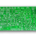
PCB Warpage, Copper Thickness and Impedance: Key Metrics Guide
Three Metrics That Define PCB Quality
Appearance alone cannot tell whether a bare board will meet the performance and reliability demands of the final product. PCB quality depends on mechanical behavior, electrical performance, material properties and manufacturing control, and three parameters deserve special attention from engineers, buyers and electronics manufacturers: pcb warpage, copper thickness and impedance. Warpage controls mechanical flatness and SMT assembly reliability, copper thickness drives current capacity, conductor resistance and heat spreading, and impedance governs high-speed transmission, signal integrity and RF performance. High-speed, high-frequency, automotive, communication, industrial control and other demanding boards normally specify all three tightly, and each one is shaped by stack-up, materials and process before it ever reaches a test machine.
Key PCB Technical Parameters
A complete set of PCB technical indicators defines structure, dimensions, electrical behavior, mechanical properties and manufacturing quality. Common items are board thickness, layer count, warpage, twist, copper thickness, trace width and spacing, impedance and its tolerance, hole size and tolerance, via structure, surface finish, solder mask, base material, dielectric thickness, dimensional tolerance, thermal performance and electrical reliability. Consumer boards often tolerate relaxed values, while automotive, high-speed communication, RF, server, medical, industrial and aerospace boards demand tight control of dimensions, warpage, copper and impedance along with stable material properties.
What PCB Warpage Is
Warpage is the bending or deformation of a finished PCB away from an ideal flat plane. Boards are never guaranteed perfectly flat: stresses introduced during material production, lamination, etching, plating or heat treatment can make the board bow up or down. Warpage is normally considered together with twist, where the corners of the board rise in different directions so the panel takes on a propeller shape. Because SMT lines assume a flat carrier, warpage above the agreed limit disturbs solder paste printing, pick-and-place accuracy and reflow, and it is especially harmful around BGA, CSP and QFN devices whose pads must stay coplanar through the reflow cycle.
Why Flatness Affects Reliability
Visible board deformation changes the contact between component pads and PCB pads, raising the risk of cold joints, insufficient solder, opens, bridges and abnormal BGA joints during reflow. Later in the product life, the residual mechanical stress from a warped board adds solder joint fatigue, component stress and thermal-cycle risk. Warpage also breaks mechanical assembly: boards may not seat in connectors, may interfere with housings or metal frames, may prevent a heatsink from touching the die, and can develop extra stress when screws pull a bowed board flat. For automotive electronics, industrial control, servers and communication equipment these failures are unacceptable, so warpage requirements must be set at the design stage.

Main Causes of Warpage
Warpage is rarely caused by one factor; it comes from material, structure and process acting together. Uneven copper distribution is the classic culprit: when opposite sides of a board carry very different copper area, thermal processing shrinks them differently and stress unbalances. An asymmetric stack-up, with different inner and outer copper weights, core and prepreg thicknesses, resin content or copper coverage, adds the same risk. Lamination pressure, temperature profile, cooling rate and panel design also influence final flatness. Balanced copper, symmetrical stacking and controlled lamination are the practical levers, which is why copper balance is a standing rule for multilayer boards.
Copper Thickness and Current
Copper thickness is normally stated in ounces per square foot, with 1 oz, about 35 microns nominal, being the most common specification, alongside 0.5 oz, 1.5 oz, 2 oz and heavier builds. Thicker copper increases current capacity and lowers trace resistance, which helps power stages run cooler, but it also makes etching, plating and fine-line control harder. Heavy copper forces wider minimum spacing and larger features, so a board that needs 3 oz on power paths and fine digital traces is usually designed with mixed copper or separate layers. The right copper weight balances real current, allowable temperature rise, trace width and the factory’s manufacturing capability instead of blindly maximizing thickness.
Impedance and Signal Integrity
Impedance describes how a controlled trace behaves as a transmission line, and it is decided by trace width, copper thickness, dielectric thickness, dielectric constant and the distance to the reference plane. High-speed interfaces require a defined characteristic impedance, commonly 50 ohm single-ended and 90 or 100 ohm differential, because impedance mismatch causes reflection, ringing and timing problems. The manufacturer normally verifies impedance with test coupons processed together with the production panel, comparing measured values with the target and tolerance. Because real impedance shifts with material and etch tolerance, the stack-up and impedance targets must be confirmed before production rather than discovered after delivery.

How the Three Interact
Warpage, copper and impedance are not independent. The stack-up chosen for impedance control fixes core and prepreg combinations that also affect flatness; copper weight set for current capacity changes etch behavior, spacing and plane continuity that feed impedance control; and the dielectric materials picked for stable Dk and low Df also influence thermal stress and warpage. A specification that treats each number in isolation usually fails in production. OEMs, design houses and buyers should therefore confirm layer count, thickness, material, copper, line and space, warpage, impedance, hole size, finish, dimensional tolerance and test requirements together, ideally in one technical review with the manufacturer before volume runs.
Practical Questions
Acceptable warpage has no universal number: it depends on board size, thickness, layers, SMT process, package types, BGA count, application environment, customer criteria and applicable standards, so the limit should be written into the order. Standard copper is 1 oz nominal; thicker copper helps current but complicates fine features. Impedance is verified through test coupons against the target. Warpage is best reduced by balanced copper, symmetric stack-up, dimensionally stable material, controlled lamination and careful panel design, starting with a design-stage risk review. When these points are settled early with a capable PCB manufacturing partner that also offers PCB design and layout support, prototypes reach volume with higher first-pass yield.
Building the Specification With Your Supplier
Every demanding program should close these parameters before production. Send the factory layer count, board thickness, material grade, copper weight, minimum line and space, warpage limit, impedance targets and tolerances, hole structure, finish and test requirements, and ask for an engineering review of the stack-up. A supplier that couples industrial PCBA services with fabrication can relate board flatness and impedance to real assembly yield, while PCBA testing verifies the assembled product rather than only the bare coupon. Early review of material, copper and stack-up choices is the cheapest insurance against late warpage and impedance failures in volume production.
PCB Key Metrics FAQ
Q1: Which PCB technical indicators matter most? It depends on the application, but common ones are thickness, layers, copper weight, line and space, warpage, impedance, material, hole size, finish and dimensional tolerance; high-speed boards add Dk, Df and signal integrity.
Q2: What warpage value is acceptable? There is no universal figure; the limit depends on size, thickness, assembly process, packages and standards, so it should be agreed per project.
Q3: What is the standard copper thickness? 1 oz, about 35 microns, is the most common specification.
Q4: Is thicker copper always better? No; thicker copper improves current and resistance but complicates etching, plating and fine-line spacing, so it must match real requirements.
Q5: How is PCB impedance tested? Manufacturers verify it with impedance coupons processed with the panel and compare results with the design target and tolerance.
Conclusion
PCB warpage, copper thickness and impedance summarize the mechanical, electrical and manufacturing quality of a board, and all three trace back to stack-up, material and process decisions. Flat boards assemble reliably, correctly specified copper carries its current without sacrificing fine features, and controlled impedance keeps high-speed signals clean. Define these metrics together with layer count, material, finish and tolerances before production, and boards come back right the first time.