Reflow Profile Development and Control
A reflow profile is the temperature history the assembly experiences as it passes through the oven, and it decides whether the solder forms a sound joint or merely melts. Building one is an exercise in satisfying several constraints at once: the alloy needs to reach liquidus, the flux needs to be active at the right moment, the components must not be damaged and the thermal mass of the board must be respected. A profile that works on the first article may still be wrong for the fourth product on the same line.
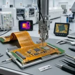
<img src="https://www.gopcba.com/wp-content/uploads/2026/04/PCB-Manufacturing.png" alt="Thermocouple attached to a board in a reflow oven” />
Starting from the Materials
The profile has to be derived from the paste and the components rather than from a template. The alloy sets the melting temperature and therefore the minimum peak, the flux chemistry sets the activation range and therefore the soak, and the components set the maximum temperature and the total time at temperature they can tolerate. Reading the paste datasheet with the component specifications side by side is the only reliable starting point, and it usually narrows the available window considerably.
The result is a window rather than a setpoint: a minimum and maximum peak, a range for time above liquidus and a range for the ramp rates. Every subsequent decision, including conveyor speed, zone temperatures and the choice of atmosphere, has to keep the assembly inside that window. Solder alloy selection determines how much room the profile has to work with in the first place.
Ramp, Soak and Peak
The preheat ramp brings the board up without thermal shock and without activating the flux too early. The soak, where it exists, holds the assembly in a band below liquidus so that the flux can clean the surfaces and the board can reach a uniform temperature, which matters most when the assembly carries components of very different mass. A profile with too short a soak arrives at liquidus with cold areas still lagging, and those areas produce the wetting defects.
The peak has to exceed liquidus by enough to guarantee complete melting at every joint while staying below the damage threshold of the most sensitive component. For lead free alloys the margin above liquidus is comparatively small, which is why peak control is a more demanding task than it was with tin lead. Profile measurement is what proves the margin exists rather than assuming it does.
Time Above Liquidus
Time above liquidus controls the formation and growth of the intermetallic layer and the completeness of wetting. Too short and some joints are still partly solid when the board leaves the last zone, producing cold joints and poor fillets. Too long and the intermetallic layer becomes thick and brittle, the flux is consumed, and in extreme cases the laminate begins to degrade. The target is usually a window of tens of seconds rather than an exact value.
The measured time must come from the slowest point on the assembly, not the fastest. A large connector, a ground plane or a heavy component attached to a thermal pad can lag the small parts by many seconds, so a profile measured at a convenient thermocouple location will overstate the margin that the critical joints actually have. Placing the thermocouple is therefore part of the engineering, not part of the setup.

Atmosphere and Oven Effects
Nitrogen reduces oxidation and widens the process window, particularly for lead free alloys and for assemblies with fine-pitch components, at the cost of gas consumption and of an additional variable to control. Where nitrogen is used, the oxygen concentration should be measured and recorded, because a small leak can quietly return the atmosphere to air while the chart still looks correct. Nitrogen reflow is worth considering where wetting defects dominate the defect pareto.
The oven itself contributes to the result. Zone temperatures are measured by the oven’s own sensors, which sit near the heaters rather than at the board, and the difference between the two grows as the oven loads up. A profile developed on an empty oven will not be the profile the product sees on a full conveyor, so verification should be done with a representative load and repeated when the product mix changes significantly.
Verifying on the Real Assembly
Verification means attaching thermocouples to a real board, at the locations that matter, and running it through the oven under production conditions. The board should carry the same components as the product, including the heaviest and the most thermally sensitive, and the thermocouples should be attached with a method that survives the conveyor without adding thermal mass of its own.
The resulting curve is compared with the window derived from the materials, and any excursion is investigated rather than tolerated. It is good practice to keep a reference board with permanently attached thermocouples for periodic checks, since it removes the variation in attachment technique between operators and makes the profiles directly comparable. Reflow profile practice covers the attachment details that most affect the measurement.
Control and Documentation
Once a profile is approved it becomes a process parameter with a revision, and any change to it should follow the same route as a change to a drawing. The oven recipe, the conveyor speed, the atmosphere setting and the thermocouple locations are recorded together, and the record is available to the operator who has to set the machine on the next shift. Without that, the approved profile survives only as long as the person who developed it.
Periodic verification, typically at each product changeover and on a defined calendar interval, keeps the process honest. Ovens drift as elements age and thermocouples degrade, and the drift is slow enough to go unnoticed until a defect appears. Recording each verification, with the measured peak and time above liquidus, produces a trend that shows the drift before the joints do.
Profiles for Mixed Assemblies
Mixed assemblies are the difficult case. A board with a small logic section and a large power section may need a profile whose peak suits the small parts while giving the heavy parts enough time to reach liquidus, and the compromise shows up as cold joints on one side and a temperature excursion on the other. The usual solutions are to add thermal mass deliberately on the light side, to extend the soak so that all areas start the final ramp from a similar temperature, or to move the heavy part to a second process step.
Where the product contains a component with a hard temperature limit, such as an electrolytic capacitor or a plastic connector, the profile can sometimes be reshaped to protect it without sacrificing the joints. Shielding that component, shortening the time above liquidus or selecting a lower melting alloy are the standard options, and each has a cost that should be evaluated before the profile is frozen.
FAQ
How many thermocouples should a profile use? Enough to cover the fastest and slowest points on the assembly, plus any component close to its temperature limit. Three to six channels is typical for a mixed assembly.
Can one profile cover several products? Sometimes, if their thermal masses and component limits are similar. Any product with a heavy connector or a large ground plane should be verified on its own.
How often should the profile be re-verified? At each changeover, after any oven maintenance, and at a defined interval such as monthly for a stable product.
What is the most common profiling mistake? Measuring on a bare board or at a convenient location rather than on the slowest joint of a fully populated assembly under production load.