Component Shift After Reflow and How to Prevent It
A component that has shifted during reflow is a placement problem that the placement machine cannot fix. The part was in the correct position when it was placed and moved while the alloy was molten, so the cause lies in the print, the profile or the mechanical environment of the oven. Because the movement happens after the placement inspection, it is often attributed to the machine incorrectly. This article covers the mechanisms and the controls.
When the Component Can Move
A component can only shift while the alloy beneath it is liquid. That window is defined by the time above the melting point, so a profile with a longer liquid time gives the part more opportunity to move and a profile with a shorter one gives it less. The window also determines how much the surface tension of the molten fillets can pull the part back into alignment.
The movement therefore has two components: a driving force that displaces the part and the self alignment that may correct it. A part that shifts and stays shifted usually had a driving force that persisted, while a part that shifts slightly and returns is showing the natural centring effect of surface tension.
Paste Volume Asymmetry
An unequal paste volume on the two sides of a component produces an unequal force when both sides melt. The larger fillet pulls harder, and the component moves toward it. Because the volume difference needed to cause movement can be small, the print has to be controlled on a per component basis rather than on the board average.
The asymmetry can come from a partially clogged aperture, from a stencil that is not flat against the board or from a paste that is not uniform. It can also come from a pad design where the two pads differ, which produces different volumes for the same aperture. Where the shift is consistent in one direction on every board, the print or the design is the most likely cause. The print measurement approach is described in solder paste inspection.

Placement Offset and Its Limits
A component placed with an offset sits with more of its termination over one pad. When the alloy melts, the forces are unbalanced and the part moves further in the same direction, which amplifies the original error rather than correcting it. The placement offset that is acceptable for electrical continuity is therefore larger than the offset that is acceptable for reflow behaviour.
The offset should be measured on the placed board rather than inferred from the machine specification, because the machine performance depends on the feeder, the nozzle and the component. Where a product shows a consistent shift, measuring the placement position on a sample before reflow separates a placement problem from a paste problem.
Conveyor Vibration and Mechanical Disturbance
Any vibration while the alloy is molten moves the components. The conveyor drive, a worn bearing, a fan imbalance or a board that is not supported as it crosses a transfer point all produce movement, and the effect is largest on the lightest components. A part that is heavy enough to resist the vibration is not affected, which is why the defect can appear specific to one component type.
The mechanical condition of the oven should therefore be checked when a shift problem appears without a print explanation. Belt tension, roller condition and the support of the board through the transfer points are the first items, and the board support considerations are the same ones described for PCB warpage control.
Outgassing and Moisture
A board or a component that contains absorbed moisture releases vapour during heating, and the vapour can push against a component. The effect is strongest for a part that covers an area where the vapour cannot escape, such as a large component on a via or on a plane. The movement can be sudden and large, which is why moisture sensitive parts must be dried before assembly.
The symptom of outgassing is a component that has moved a large distance or that is tilted, often with voids in the joint. Where that pattern appears, the storage and baking history of the board and the parts should be reviewed rather than the placement or the print settings. The handling requirements for moisture sensitive parts are part of the process control described in component selection beyond the datasheet.
Profile, Cooling and Self Alignment
The profile determines how much opportunity the part has to move and to correct itself. A slow ramp and a controlled soak allow the flux to activate and the alloy to melt uniformly, while a fast ramp produces unequal melting and more movement. A long time above liquidus gives the surface tension more time to centre the part but also more time for a driving force to act.
Cooling matters because a component that is still mobile as the alloy freezes can be left slightly displaced. A slow cooling allows the alloy to solidify uniformly, while a fast cooling can freeze one side first and pull the part toward it. The balance between the two parts of the profile should be established on the actual assembly.
Detection and Corrective Sequence
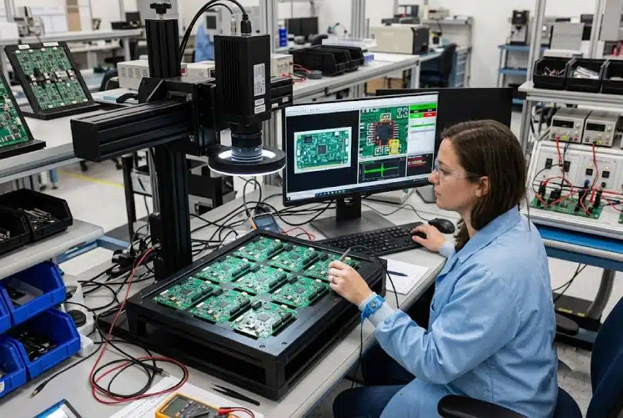
Detection is visible and optical inspection is effective, since the shift is present after reflow. The corrective sequence should follow the evidence: measure the paste volume on both sides, measure the placement position, check the oven mechanically, then review the profile. Changing the profile first is common and usually ineffective, because the driving force remains.
The gopcb assembly group classifies component shift separately from placement error, because the two have different causes and different owners. Tracking the rate by component type and by direction shows whether the problem is concentrated on one part of the board, which is the fastest route to the cause.
Checks Before Release
The sequence of operations is part of the specification, because a different order produces a different result from the same steps. Where the process window is narrow, the measurement resolution has to be better than the window, or the data cannot distinguish a good part from a marginal one.
FAQ
Is component shift the placement machine fault? Not usually. The part is normally placed correctly and moves during reflow. Placement offset contributes by making the forces unbalanced.
Can surface tension realign a component? It can, within limits. A part with a small error is often pulled back to the centre of its pads, which is why a small offset does not always produce a defect.
Why does only one component type move? Because the driving force scales with the component mass and the pad area. The lightest part on the smallest pads has the least resistance.