Thermal Shock Testing for PCBs and Assembled Boards
Thermal shock testing puts a finished board through rapid temperature changes to see whether the plated holes, the laminate and the solder joints survive them. It is a destructive test, it is slow, and it is one of the few checks that answers the question a customer actually asks: will this board still work after ten years of heating and cooling. This article explains how the test is run and how the results are read.
What Thermal Shock Tests Reveal
The test accelerates the differential expansion between copper, resin and solder. Because those materials expand at different rates, every temperature change loads the interfaces between them, and a weak interface fails long before a strong one.
The test is also the reason barrel plating thickness and ductility are specified at all, because a plated barrel that looks acceptable in cross section can still crack after a few hundred cycles.
The result is a measure of process quality rather than of design alone. Two boards with identical designs can behave very differently if one has thin barrel plating or a poorly prepared hole wall, which is why the test is used as a process monitor.
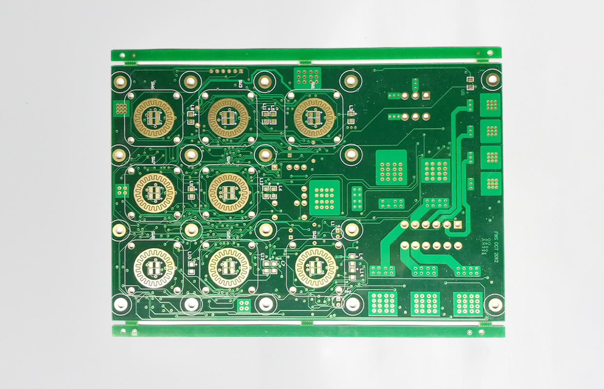
Because the test is destructive, it is applied to coupons and samples rather than to product, and the coupon must be processed alongside the panels it represents.
Shock Versus Cycling: Different Mechanisms
Thermal shock moves the sample rapidly between two temperature extremes, so the failure mechanism is dominated by the rate of change. Cycling uses slower transitions and longer dwells, which allows creep and fatigue to develop over many cycles.
The two tests find different problems. Shock tends to expose barrel cracks and plating adhesion failures, while thermal cycling exposes fatigue cracks in solder joints. A qualification programme usually includes both, since passing one says nothing about the other.
Test Conditions and Transfer Time
Typical conditions for an electronics shock test are minus forty degrees to plus one hundred and twenty five degrees, with a dwell long enough for the sample to reach the extreme and a transfer time under a minute. The exact figures come from the applicable standard or from the customer specification.
Dwell time is the parameter most often shortened in practice, and it is the one that changes the result most. A sample that has not reached the cold extreme has not experienced the strain the test is supposed to apply, so the boards pass for the wrong reason.
<img src="https://www.gopcba.com/wp-content/uploads/2026/09/224-1.jpg" alt="Microsection of a plated hole after thermal shock testing” />
Failure analysis is most useful when it goes back to the process. A barrel crack with a rough, nodular wall points to plating chemistry, one with a resin void behind it points to hole wall preparation, and one that follows the fibre pattern points to drilling. Reading the failure in those terms turns a pass or fail result into a corrective action.
Sample loading matters too. Boards stacked loosely in a basket see different airflow from boards held in a rack, and the difference shows up as variation within a single run.
Coupon Design and Sample Preparation
The coupon should contain the smallest hole on the panel, the thickest board section and the same plating process as the product. A coupon with generous holes and minimal plating will pass a test that the product fails.
Samples are normally taken from several positions across the panel so that the variation within the panel is represented. Reading only the centre hides edge effects that are often the first to fail.
Evaluation by Microsection
After the cycles, samples are mounted, ground and polished to expose the plated holes. The evaluation looks for barrel cracks, corner cracks, plating separation and resin voids, and it is done under magnification against a reference standard.
Sectioning technique affects what is seen. Poor polishing rounds the edges of a crack or smears copper across it, and a badly mounted sample can show artefacts that look like defects. Consistency between operators matters as much as the magnification used.
Failure Modes Found in Plated Holes
The classic failure is a crack running around the barrel, usually at the corner where the hole meets the surface pad. It starts as a hairline separation and grows until the connection opens, and it is the reason barrel plating thickness and ductility are specified.
Other modes include separation between the plating and the inner layer copper, resin voids behind the barrel and cracks that follow the glass fibres in the laminate. Each points to a different process step: plating quality, hole wall preparation or drilling damage.
Assembly Level Shock Testing
Test frequency is usually tied to reliability class rather than to output. A high reliability product may be tested every lot, while a general product is tested when the process changes, when a new laminate is introduced or at a quarterly interval. The trigger conditions should be written down so the test is not skipped during a busy period.
At assembly level the same test is run on populated boards, where solder joints rather than plated holes are the weakest link. Components with a large thermal mass or a large expansion mismatch relative to the board are the ones that fail first.
Evaluation combines electrical test after the run with microsectioning of selected joints. Electrical test alone can miss a partially cracked joint, and sectioning alone can miss a failure that only appears under load.
Acceptance Criteria and Interpretation
Acceptance is usually expressed as a maximum crack length or as a percentage of the plated wall that may be affected, with photographic references for the boundary cases. The criteria should state the magnification and the measurement method so the judgement is repeatable.
The most useful interpretation is comparative. A board that passes today and fails in three months under the same conditions tells you the process changed, even if the absolute result is still inside the limit.
Records and Frequency
Records should include the equipment, the profile, the sample positions, the number of cycles and the sectioning result, filed against the lot. Without the profile, a result cannot be compared with an earlier one, because a different dwell or transfer time changes the severity of the test.
gopcb runs thermal shock as part of routine process monitoring on high reliability product, using coupons that travel with the panels and sectioning evaluated against a written standard. The test coupon is what connects the product to the result, and the quality record is what makes it useful months later.
Points to Confirm at First Article
Where a decision is made by judgement, a boundary sample makes the judgement repeatable between operators and between shifts. Where a process is at the edge of its capability, the margin should be bought deliberately rather than discovered during production.
FAQ
How many cycles are enough? The number comes from the standard or the customer requirement, and it should be stated with the profile. Comparing results from runs with different dwell times is not meaningful.
Can thermal shock be replaced by a bake? No. A bake applies temperature without the differential strain that produces barrel cracks, so it tests something different.
Why do results vary between panels? Position within the panel, plating thickness, hole size and drilling quality all vary. Sampling several positions and sectioning more than one hole gives a representative answer.