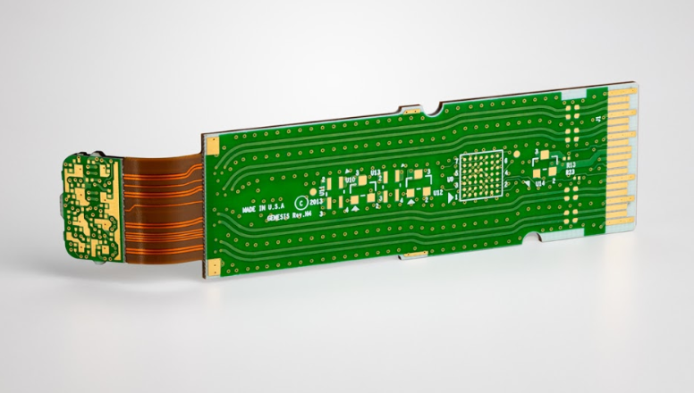
Functional Test Fixture Design and Upkeep
A functional test fixture holds the assembly, connects it to the test equipment, and lets the test programme exercise the product the way it will be used. It is a piece of equipment in its own right, with an alignment tolerance, a wear life and a maintenance requirement, and it is often the least documented item on a test floor. When a fixture drifts, the symptom is a change in the pass rate that gets attributed to the product rather than to the interface.
What a Functional Fixture Has to Provide
The fixture has to locate the assembly repeatably, make every connection the test needs, supply power and stimulus, and read the responses without adding noise or loading the circuit. It also has to do this without damaging the board, which means controlling the force at each contact point and supporting the board where the force is applied. Those requirements pull against each other: a firm contact is reliable and a firm contact flexes the board.
The connection set defines the fixture. A power and signal interface through a connector needs only a mating connector and strain relief; a board that has no connector needs probes on test points; a radio product may need a shielded enclosure and an antenna coupler. The fixture design follows from that list, and the list should come from the test requirements rather than from what the previous fixture happened to do.
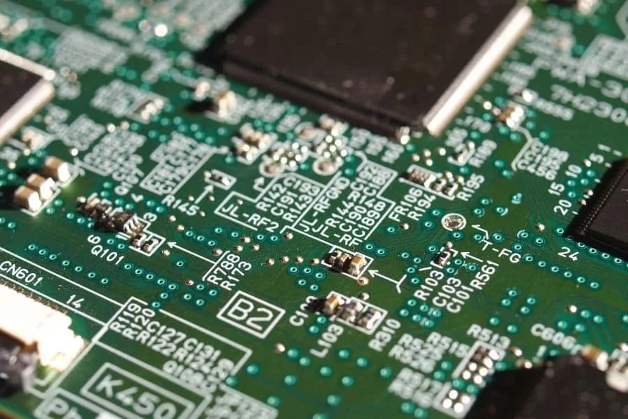
Interface and Pogo Pin Selection
A pogo pin has a barrel, a plunger and a spring, and its ratings cover current, contact resistance, travel and life. The current rating is set by the barrel and the plunger, the resistance by the plating and the contact force, and the life by the plating and the travel. A pin used at its maximum current will run warm and lose its spring more quickly, so the selection should leave a margin.
The tip geometry should match the target. A sharp tip penetrates oxide and makes a good contact on a bare pad, at the cost of marking it; a flat or crowned tip spreads the force and is better on a plated hole or a test point that must stay unmarked. Where the same fixture tests boards with different finishes, the tip should be chosen for the least forgiving one rather than for the average. The pin’s travel should be set so that it is compressed to the middle of its range when the fixture is closed, which leaves room for both board thickness variation and wear.
Cabling, Shielding and Grounding
The wiring carries the signals and it also carries noise. A long unshielded lead to a sensitive node picks up whatever is in the room, and the resulting measurement is a property of the fixture rather than of the product. Sensitive signals should be routed in shielded cable with the shield grounded at the instrument end, and the routing should avoid running alongside switching supplies and motor drives.
Grounding needs a defined scheme rather than a connection to whatever is convenient. A single-point ground for the analogue reference and a separate return for the power currents prevents the power current from developing a voltage along the signal reference. Where the test measures a small voltage, that difference is the dominant error, and it appears as a drifting reading that changes when the load changes. The scheme should be drawn on the fixture schematic, not left to the wireman.
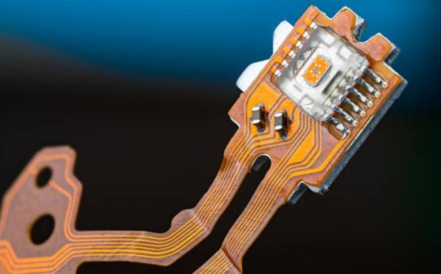
Fixture Alignment and Repeatability
The fixture locates the board by its tooling holes or its outline, and the repeatability of that location sets the repeatability of every probe contact. A locating pin that is a loose fit, a stop that is worn, or a clamp that pulls the board sideways on closing will all move the contact points. The result is a fixture whose contact resistance varies, which shows up as intermittent test failures.
Fixture repeatability should be verified by testing the same board several times, removing and replacing it between tests. A variation in the measured values that is larger than the test limit indicates a locating problem rather than a product problem. The check is quick and it should be done when the fixture is commissioned and after any change to the locating hardware. Where the fixture holds several boards at once, the repeatability should be checked at each position, because the position that is worst is the one that sets the limit.
Maintenance and Wear Items
The wear items are the pogo pins, the locating pins, the clamps, the cables and the connectors. Pogo pins wear at the tip and lose spring force; their contact resistance rises gradually, and the rise is visible if the fixture is checked on an interval. Locating pins wear at the bearing surface, clamps lose their travel, and cables fail at the point where they flex.
The maintenance should be scheduled and recorded, with the pins replaced on a defined interval or when their resistance exceeds a limit. Where a fixture is used on several products, the interval should follow the total number of closures rather than the calendar. The test fixture maintenance notes describe the checks and the records, and the fixture guide covers the design decisions that make the maintenance easier.
Fixture Verification and Correlation
Before a fixture is released, it should be verified against a known-good board and against a board with a known defect. The known-good board confirms that the fixture does not produce false failures; the defective board confirms that it can detect the defect it is intended to detect. Both results should be recorded with the fixture identifier.
Correlation matters where two fixtures test the same product on different lines. The two should produce the same result on the same board, within a defined tolerance, and the correlation should be re-checked when either fixture is modified. Where the results differ, the measurement difference should be quantified rather than reviewed as a pass or fail, so that the fixture with the error can be identified. The engineering test station arrangements are usually where this correlation work is done.
Multiple Products on One Fixture
A fixture shared between products saves cost and introduces risk. The locating scheme has to suit every board, the probe positions have to avoid conflicts, and the test programme has to know which product is present. Where the products have different thicknesses, the probe compression changes between them, and a setting that suits one may overload the other.
The safe arrangement is a changeable nest or a changeable probe plate, so that the interface between the product and the fixture is specific to the product while the frame and the instrumentation are shared. The changeover should be verified with the same known-good board check as a new fixture, because a nest that is not seated correctly produces a fixture that looks right and tests wrongly. Records should identify which nest was fitted for which lot.
Documentation and Change Control
The fixture documentation should include the schematic, the probe list with the net each pin contacts, the locating arrangement, the maintenance schedule and the verification records. The probe list is the item that is most often missing and the most useful, because it allows a failing pin to be traced to a net without dismantling the fixture.
Changes to a fixture should be controlled in the same way as changes to a test programme. Adding a probe, moving a stop or altering the grounding changes what the fixture measures, and the change should be recorded with the reason and the verification. Where a fixture is modified to fix a production problem, the modification should be reviewed against the correlation with the other fixtures before it is released. The hipot test arrangement, where it exists, is a good example of a fixture feature whose safety and correctness depend on the earth path being documented rather than assumed.
FAQ
How often should pogo pins be replaced? On a closure count that follows the maker’s life rating, shortened where the pins are used at high current or on a rough surface. The replacement should also be triggered by a rise in contact resistance, which is the measurement that shows the wear before it becomes a failure.
Can a fixture be used without a known-good board? It can be released, but the verification is incomplete, because a fixture that fails everything and one that fails nothing look the same without a reference. A known-good board and a known-bad board are the minimum set.
Does the fixture affect the measurement of a low-level signal? It does, through the lead resistance and the pickup, and both are properties of the fixture rather than of the product. Where the tolerance is tight, the fixture should be characterised before the test limit is set, so that the limit reflects the product and not the fixture noise.