Modern vehicles are no longer powered by mechanical systems alone. Electronics have become the foundation of vehicle control, safety, connectivity, electrification, and intelligent driving. From engine control units and battery management systems to advanced driver assistance systems, infotainment, radar, cameras, and vehicle networking, modern automobiles rely on a growing number of sophisticated electronic control modules.
Every electronic control unit requires a reliable automotive PCB capable of operating under demanding conditions. Unlike consumer electronics, automotive circuit boards may need to withstand extreme temperatures, continuous vibration, mechanical shock, humidity, electromagnetic interference, and long operating lifecycles.
As vehicles become increasingly electrified and intelligent, the requirements for automotive PCB design, automotive PCB manufacturing, and automotive PCB assembly continue to become more demanding.
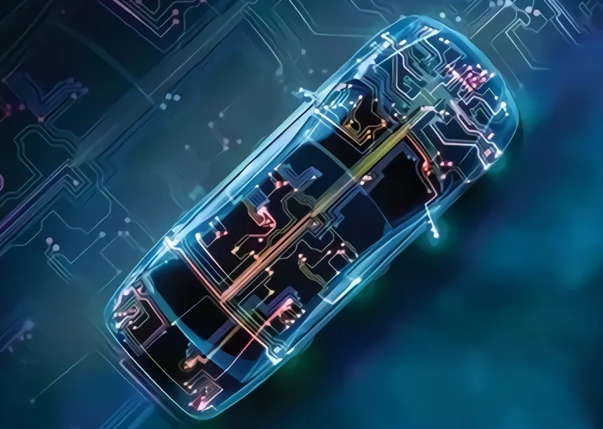
A successful automotive PCB design must balance electrical performance, thermal management, mechanical reliability, manufacturability, cost, and functional safety. A design problem that might cause inconvenience in consumer electronics can have much more serious consequences in automotive applications.
This guide explains the major types of automotive PCBs, key design challenges, engineering practices, applicable standards, manufacturing considerations, cost factors, and how an experienced manufacturing partner such as Kingda can support automotive electronics development from prototype to production.
Key Takeaways
- Automotive PCBs must withstand vibration, temperature extremes, moisture, and electromagnetic interference.
- PCB construction should be selected according to the application’s thermal, mechanical, electrical, and space requirements.
- Rigid PCB, flex PCB, rigid-flex PCB, metal-core PCB, and HDI PCB technologies serve different automotive applications.
- Proper component placement, grounding, controlled impedance, and signal routing are essential for reliable automotive electronics.
- AEC-Q100, IPC-6012, IATF 16949, and ISO 26262 address different aspects of automotive electronics and manufacturing.
- Thermal management and moisture protection become particularly important in EV, power electronics, and under-hood applications.
- Early DFM review and integrated PCB fabrication and assembly can reduce manufacturing risks and unnecessary design iterations.
- Kingda provides PCB manufacturing, PCB prototyping, quick-turn PCB services, and PCB assembly solutions to support automotive electronics development.
Types of Automotive PCBs Used in Vehicles
Different automotive electronic systems operate under different environmental and electrical conditions. Therefore, there is no single PCB technology suitable for every automotive application.
Selecting the appropriate automotive PCB type at the beginning of the design process can significantly influence reliability, performance, and manufacturing cost.
Rigid PCBs
Rigid PCBs are among the most widely used circuit boards in automotive electronics. They provide mechanical stability and are suitable for applications where the PCB does not need to bend or move during operation.
Typical applications include:
- Engine control units (ECUs)
- Transmission control modules
- Instrument clusters
- Dashboard electronics
- Infotainment systems
- Camera control modules
- Body control modules
- Power management electronics
FR-4 remains a common material for many automotive applications. However, material selection should consider operating temperature, thermal cycling, electrical performance, and reliability requirements rather than simply selecting a standard FR-4 material.
For high-temperature environments, designers may need high-Tg or other specialized laminate materials to improve thermal reliability.
Flexible PCBs
Flexible PCBs, or flex circuits, are designed for applications where space is limited or the circuit needs to bend during installation or operation.
Automotive flexible PCBs can be used in:
- Steering column electronics
- Sensor assemblies
- Lighting systems
- Display modules
- Camera modules
- Door and interior electronics
- Instrumentation systems
Flex circuits can reduce wiring complexity and provide greater freedom in three-dimensional electronic packaging.
However, flexible PCB design requires careful consideration of bend radius, copper construction, mechanical stress, stiffener placement, and repeated-flex requirements.
Rigid-Flex PCBs
Rigid-flex PCBs combine rigid board sections with flexible circuit sections.
This technology is particularly useful for automotive applications where electronic components need to be installed in compact or irregularly shaped spaces.
Advantages include:
- Reduced connector count
- Reduced wiring complexity
- Improved packaging flexibility
- Better resistance to vibration-related connection problems
- Three-dimensional installation capability
- Reduced overall assembly space
Rigid-flex technology can be particularly valuable in applications involving steering systems, lighting, sensors, displays, and compact control modules.
Metal-Core and LED PCBs
Automotive lighting systems generate significant heat, particularly high-power LED applications.
Traditional FR-4 may not provide sufficient thermal performance for some high-power applications. Metal-core PCBs, including aluminum-based PCB constructions, can improve heat transfer away from high-power components.
Typical applications include:
- Headlights
- Daytime running lights
- Brake lights
- Turn indicators
- Interior lighting
- High-power LED modules
Thermal design should consider not only the PCB material but also copper thickness, thermal vias, heat spreaders, mounting structures, and the overall thermal path.
Multilayer and HDI PCBs
As automotive electronic systems become smaller and more powerful, designers increasingly rely on multilayer PCB and HDI PCB technologies.
These technologies provide higher routing density and allow more electrical functions to be integrated into smaller packages.
Typical applications include:
- ADAS modules
- Radar systems
- LiDAR electronics
- Vehicle networking
- High-speed communication modules
- Infotainment systems
- Advanced computing platforms
HDI PCB technology can support microvias, fine-line structures, via-in-pad configurations, and high-density component placement.
For high-frequency automotive applications, material selection and controlled impedance become especially important because even small variations in dielectric properties or trace geometry can affect signal integrity.
How to Select the Right Automotive PCB
The correct PCB technology should be selected according to actual application requirements.
Consider the following factors:
| Application Requirement | Recommended PCB Consideration |
|---|---|
| Standard ECU | Rigid multilayer PCB |
| Tight installation space | Flex or rigid-flex PCB |
| High-power LED | Metal-core or thermally optimized PCB |
| Radar/high-speed communication | High-frequency or HDI PCB |
| High component density | Multilayer or HDI PCB |
| High vibration environment | Mechanically robust rigid or rigid-flex PCB |
| High-temperature environment | High-Tg or specialized laminate |
The most advanced PCB technology is not necessarily the best choice for every application. Selecting the appropriate construction according to actual electrical, thermal, mechanical, and cost requirements is more effective than overengineering the board.
Major Automotive PCB Design Challenges
Automotive electronics operate in environments that can be significantly more demanding than ordinary consumer electronics.
Engineers must consider several major challenges during automotive PCB design.
1. Temperature Extremes and Thermal Cycling
Automotive electronics can experience significant temperature variations depending on their installation location.
Under-hood electronics may be exposed to high temperatures, while other modules inside the passenger compartment may operate under considerably less demanding conditions.
Thermal design should consider:
- Maximum operating temperature
- Minimum operating temperature
- Thermal cycling
- Component temperature ratings
- PCB material Tg
- Copper thickness
- Heat dissipation
- Thermal vias
- Heat sinks
- Component spacing
Automotive-grade components are often selected according to their qualified operating temperature range.
The PCB itself must also be capable of maintaining mechanical and electrical reliability throughout repeated temperature changes.
Repeated expansion and contraction can create stress in solder joints, vias, copper structures, and laminate materials.
2. Vibration and Mechanical Shock
Vehicles continuously experience vibration and mechanical shock from road conditions, engine operation, acceleration, braking, and other mechanical forces.
Therefore, automotive PCB reliability depends heavily on mechanical design.
Potential failure mechanisms include:
- Cracked solder joints
- Component fatigue
- Via failures
- Copper cracking
- Connector damage
- Laminate delamination
PCB thickness, mounting location, component weight, solder joint design, and mechanical reinforcement should all be considered during the design stage.
For applications exposed to severe vibration, designers should avoid unnecessary mechanical stress concentrations and carefully evaluate large or heavy components.
3. EMI and EMC
Automotive systems increasingly combine high-speed digital circuits, wireless communication, sensors, power electronics, and high-current systems in relatively small spaces.
This creates significant EMI and EMC challenges.
Potential sources of interference include:
- Switching power supplies
- EV inverters
- Motors
- DC-DC converters
- High-speed processors
- Wireless modules
- Radar systems
- CAN and automotive Ethernet interfaces
Poor PCB layout can increase electromagnetic emissions or make sensitive circuits more vulnerable to external interference.
Effective EMI/EMC design may include:
- Continuous ground planes
- Proper layer stack-up
- Controlled return paths
- Differential routing
- Appropriate shielding
- Short high-current loops
- Proper decoupling
- Separation of noisy and sensitive circuits
4. Thermal Management in EV and High-Power Electronics
Electrification is increasing the power density of automotive electronics.
EV-related systems such as battery management systems, onboard chargers, DC-DC converters, and inverter control electronics may generate substantial heat.
A PCB thermal design should provide an efficient path for heat to move from components into the PCB and ultimately into the vehicle’s cooling structure.
Important techniques include:
- Increased copper thickness
- Thermal vias
- Large copper areas
- Metal-core PCB construction
- Heat spreaders
- Heat sinks
- Thermally optimized component placement
Thermal simulation and prototype testing can help verify whether the proposed thermal solution is adequate.
5. Miniaturization and Space Constraints
Automotive manufacturers continue to integrate more electronic functionality into smaller modules.
This creates pressure for higher PCB density.
Designers may use:
- HDI technology
- Microvias
- Fine-pitch components
- Via-in-pad
- Multilayer structures
- Rigid-flex construction
- Smaller component packages
However, miniaturization should not compromise manufacturability or reliability.
A high-density PCB should still provide sufficient clearance, thermal performance, inspection accessibility, and assembly process margin.
6. Moisture and Environmental Protection
Automotive electronics may be exposed to humidity, condensation, water, chemicals, and contaminants.
Moisture can contribute to:
- Corrosion
- Leakage current
- Electrochemical migration
- Insulation degradation
- Solder joint deterioration
Depending on the application, designers may consider conformal coating, potting, sealing, protective housings, or other environmental protection methods.
The coating material and coverage should be selected according to the operating environment and service requirements.
Essential Automotive PCB Design Guidelines
Component Placement
Proper component placement is one of the most important aspects of automotive PCB layout.
Recommended practices include:
- Place heat-generating components away from temperature-sensitive devices.
- Keep decoupling capacitors close to IC power pins.
- Group functionally related components together.
- Separate sensitive analog circuits from noisy digital or power circuits.
- Keep high-current paths short and direct.
- Consider the mechanical location of connectors and mounting points.
- Minimize unnecessary component height in constrained enclosures.
Component placement should consider electrical, thermal, mechanical, and manufacturing requirements simultaneously.
Signal Routing and the 3W Rule
The 3W rule is commonly used as a basic guideline for reducing electromagnetic coupling between adjacent traces.
It recommends maintaining a spacing of approximately three times the trace width between traces where practical.
For example, if a trace is 0.20 mm wide, a 3W guideline would suggest approximately 0.60 mm spacing between adjacent traces.
However, the 3W rule should not be treated as a universal replacement for signal-integrity analysis.
High-speed automotive interfaces may require controlled impedance calculations, electromagnetic simulation, field-solver analysis, or application-specific spacing requirements.
Additional routing practices include:
- Use controlled impedance for high-speed signals.
- Route differential pairs with consistent geometry.
- Maintain continuous reference planes.
- Minimize unnecessary vias.
- Keep high-current loops short.
- Avoid routing sensitive signals near noisy power circuits.
- Maintain appropriate separation between different signal classes.
Grounding and EMI Control
Effective grounding is essential for automotive PCB performance.
Recommended practices include:
- Use continuous ground planes where possible.
- Provide short return paths for high-frequency signals.
- Avoid unnecessary ground-plane interruptions.
- Place decoupling capacitors close to IC power pins.
- Separate high-current return paths from sensitive analog returns when required.
- Carefully control chassis and signal-ground connections.
A fragmented ground structure can increase loop area and create unwanted electromagnetic coupling.
Design Rule Checking
Design Rule Check (DRC) should be performed throughout the PCB layout process rather than only after the design is completed.
Typical DRC checks include:
- Trace width
- Trace spacing
- Via clearance
- Component clearance
- Copper-to-edge clearance
- Hole-to-hole spacing
- Differential pair rules
- Impedance requirements
- Manufacturing constraints
Early error detection is significantly less expensive than discovering a design problem after PCB fabrication or assembly.
Automotive PCB Standards and Certifications
Automotive PCB projects may involve several different standards, and each standard addresses a specific part of the product or manufacturing process.
| Standard | Primary Focus | Application |
|---|---|---|
| IPC-6012 | Qualification and performance requirements for rigid PCBs | PCB manufacturing |
| AEC-Q100 | Stress qualification of integrated circuits | Automotive components |
| IATF 16949 | Automotive quality management | Automotive manufacturing |
| ISO 26262 | Functional safety | Automotive electronic systems |
| ISO 9001 | General quality management | Manufacturing organizations |
IPC-6012
IPC-6012 establishes requirements for the qualification and performance of rigid printed boards.
For high-reliability automotive applications, PCB manufacturers need to control factors such as:
- Plating quality
- Hole quality
- Copper thickness
- Dimensional tolerances
- Electrical performance
- Structural integrity
The exact class and requirements should be selected according to the product specification.
AEC-Q100
AEC-Q100 is primarily associated with the qualification of automotive integrated circuits.
It evaluates semiconductor components under various environmental and reliability stress conditions.
It is important to distinguish AEC-Q100 component qualification from PCB qualification. A PCB manufacturer does not make the PCB itself “AEC-Q100 qualified”; rather, the components used in the assembly may have AEC-Q100 qualification.
IATF 16949
IATF 16949 is an automotive quality management standard focused on process consistency, risk management, defect prevention, and continuous improvement throughout the automotive supply chain.
For automotive PCB and PCBA projects, manufacturing process control and traceability are particularly important.
ISO 26262
ISO 26262 addresses functional safety for road-vehicle electrical and electronic systems.
It is particularly important for safety-related applications such as:
- Braking systems
- Steering systems
- Airbag systems
- Powertrain control
- Advanced driver assistance
- Other safety-critical electronic functions
PCB design and manufacturing form part of the larger system-level safety process and should therefore be managed according to the project’s functional-safety requirements.
Automotive PCB Manufacturing and Assembly Process
A reliable automotive PCB manufacturer should manage PCB fabrication and assembly with a controlled and repeatable manufacturing process.
A typical workflow includes:
Automotive PCB Design → DFM Engineering Review → PCB Fabrication → Component Sourcing → SMT Assembly → THT Assembly → Reflow/Soldering → AOI/X-Ray Inspection → Electrical Testing → Functional Testing → Final Inspection → Production
DFM Engineering Review
Before fabrication, the PCB design should be reviewed for manufacturability.
The review can identify:
- Insufficient clearances
- Difficult-to-manufacture features
- Component availability issues
- Soldering challenges
- Thermal problems
- Assembly constraints
- Testing requirements
Early DFM review can reduce unnecessary prototype iterations and improve production readiness.
SMT and THT Assembly
Modern automotive electronics may combine SMT assembly with THT assembly.
SMT is commonly used for compact electronic components, while THT may be appropriate for connectors, large components, or components requiring additional mechanical strength.
The assembly process should be selected according to the component structure and application requirements.
Inspection and Testing
Quality control is essential for automotive PCBA.
Depending on the project, inspection and testing may include:
- SPI
- AOI
- X-ray inspection
- Electrical continuity testing
- Flying probe testing
- ICT
- Functional testing
- Programming
- Visual inspection
For BGA and other hidden solder joints, X-ray inspection can provide additional visibility that optical inspection cannot provide.
How Much Does Automotive PCB Manufacturing Cost?
The cost of an automotive PCB depends on many technical and commercial factors.
Major Cost Factors
Layer Count
Increasing the number of PCB layers generally increases material and processing costs.
However, higher layer counts may be necessary to achieve:
- High routing density
- Controlled impedance
- Power distribution
- EMI control
- Signal integrity
PCB Material
Standard FR-4 is suitable for many applications, while specialized high-temperature, high-frequency, low-loss, or flexible materials may be required for demanding applications.
Material selection should be based on actual operating requirements rather than simply choosing the lowest-cost material.
PCB Size and Complexity
Board dimensions, copper thickness, minimum trace/space, via structures, surface finish, and manufacturing tolerances can all affect PCB cost.
HDI, microvias, fine-pitch features, and complex stack-ups generally require additional manufacturing processes.
Component and BOM Complexity
The number and type of components have a significant influence on automotive PCB assembly cost.
Factors include:
- Component quantity
- Package types
- BGA components
- Fine-pitch components
- Component availability
- Alternative components
- SMT/THT mix
- Special components
Testing Requirements
Automotive electronics often require more extensive inspection and validation than ordinary consumer electronics.
Testing may include:
- Electrical testing
- Functional testing
- Thermal cycling
- Vibration testing
- Environmental testing
- X-ray inspection
The exact test program should be based on the application, reliability requirements, and customer specifications.
Why Choose Kingda for Automotive PCB Manufacturing?
Choosing the right manufacturing partner is an important part of automotive electronics development.
As an experienced PCB manufacturer and PCB assembly service provider, Kingda provides integrated automotive PCB manufacturing and PCBA solutions designed to support customers from initial design validation to production.
Integrated PCB and PCBA Services
Kingda can support the complete manufacturing workflow, including:
- PCB prototype manufacturing
- Quick-turn PCB prototyping
- PCB fabrication
- Component sourcing
- SMT assembly
- THT assembly
- PCB inspection
- Assembly testing
- Small-batch production
- Production manufacturing
This integrated approach can reduce unnecessary communication gaps between PCB fabrication and assembly.
DFM and Engineering Support
Automotive PCB designs often involve strict electrical, mechanical, and manufacturing requirements.
Kingda can provide manufacturing-oriented engineering support during the DFM review stage, helping customers identify potential production issues before the boards enter fabrication.
Early engineering review can help optimize:
- PCB stack-up
- Component placement
- Routing
- Manufacturability
- Assembly process
- Component sourcing
- Testing requirements
Prototype to Production Support
Automotive product development usually progresses through multiple stages:
Concept → PCB Design → Prototype → Engineering Validation → Design Optimization → Small-Batch Production → Mass Production
Kingda’s integrated PCB and PCBA capabilities can support customers throughout this development cycle.
This continuity allows prototype results and manufacturing feedback to be incorporated into subsequent production stages more efficiently.
Component Sourcing and BOM Support
Automotive electronics may contain a large number of components with different specifications and availability requirements.
Kingda can assist with component sourcing and BOM coordination to help customers manage component requirements during prototype and production preparation.
SMT and THT Assembly
Kingda provides SMT assembly and THT assembly solutions for different PCB designs and component structures.
Combining surface-mount and through-hole technologies allows automotive PCB assemblies to accommodate compact components as well as mechanically robust connectors and larger components.
Inspection and Testing
Reliable automotive PCBA requires appropriate inspection and testing throughout the manufacturing process.
Kingda can integrate inspection and testing according to project requirements, including processes such as:
- SPI
- AOI
- X-ray inspection
- Electrical testing
- Functional testing
- Final inspection
The inspection strategy can be adjusted according to the PCB structure, component package, product application, and customer requirements.
Best Practices for Automotive PCB Development
For a successful automotive PCB project, consider the following principles:
- Define environmental requirements early.
Establish temperature, vibration, humidity, chemical exposure, and service-life requirements before PCB design begins. - Select PCB materials according to actual conditions.
Do not use specialized materials unless their electrical, thermal, or mechanical advantages are necessary. - Plan the PCB stack-up carefully.
Layer configuration affects signal integrity, power distribution, thermal performance, and EMI. - Separate noisy and sensitive circuits.
Pay particular attention to power electronics, high-speed signals, RF circuits, and analog interfaces. - Use appropriate thermal management.
Evaluate heat-generating components and provide an effective thermal path. - Design for manufacturing from the beginning.
Early DFM engineering can prevent manufacturing problems before fabrication. - Consider testing during PCB design.
Test points, programming interfaces, and functional test requirements should be considered before layout completion. - Build prototypes before mass production.
Prototype PCB assembly provides valuable feedback about electrical performance, manufacturability, thermal behavior, and reliability. - Maintain manufacturing traceability.
Automotive applications benefit from controlled processes and appropriate production records. - Work with an experienced PCB and PCBA partner.
An integrated supplier can help coordinate PCB fabrication, component sourcing, assembly, inspection, and testing.
Frequently Asked Questions
What is an automotive PCB?
An automotive PCB is a printed circuit board specifically designed for vehicle electronic systems. Compared with ordinary consumer PCBs, automotive boards typically require higher reliability and must be designed to withstand conditions such as temperature extremes, vibration, moisture, and electromagnetic interference.
What types of PCBs are used in automotive electronics?
Common types include rigid PCBs, flexible PCBs, rigid-flex PCBs, metal-core PCBs, multilayer PCBs, and HDI PCBs. The appropriate type depends on the application’s thermal, mechanical, electrical, and space requirements.
What standards are important for automotive PCB manufacturing?
Common standards and specifications include IPC-6012, AEC-Q100, IATF 16949, and ISO 26262. Each addresses different aspects of PCB manufacturing, component qualification, quality management, or functional safety.
What is the 3W rule in PCB design?
The 3W rule is a basic PCB layout guideline that recommends maintaining approximately three times the trace width between adjacent traces to reduce electromagnetic coupling and crosstalk. High-speed applications may require more rigorous signal-integrity analysis.
Why is thermal management important for automotive PCBs?
Automotive electronics can operate in high-temperature environments and increasingly handle higher power densities. Effective thermal management helps prevent excessive component temperatures, improves reliability, and reduces the risk of thermally induced failures.
How can automotive PCB costs be reduced?
Cost can be controlled through appropriate material selection, optimized layer count, efficient PCB layout, manufacturability-focused design, component standardization, efficient sourcing, and early DFM review.
Overengineering the PCB can increase cost without necessarily improving reliability. The goal should be to select the right technology for the actual application requirements.
Can Kingda support both PCB prototypes and production?
Yes. Kingda provides PCB prototype manufacturing, quick-turn PCB prototyping, PCB fabrication, and PCB assembly services, allowing customers to progress from initial design validation and prototype production toward small-batch and larger-scale manufacturing.
Conclusion
The rapid development of EVs, ADAS, connected vehicles, intelligent cockpits, and advanced vehicle computing is driving increasing demand for reliable automotive PCBs.
Successful automotive PCB development requires more than simply designing a functional circuit. Engineers must consider temperature, vibration, moisture, EMI/EMC, thermal management, miniaturization, signal integrity, manufacturability, testing, and long-term reliability from the beginning of the design process.
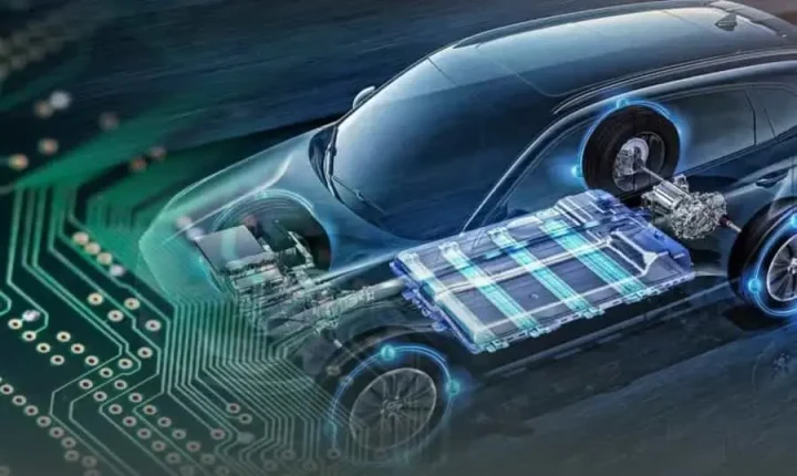
The right PCB technology should be selected according to the actual application. Rigid PCB, flex PCB, rigid-flex PCB, metal-core PCB, multilayer PCB, and HDI PCB technologies each provide different advantages.
At the manufacturing stage, an experienced partner can help integrate PCB fabrication, component sourcing, SMT assembly, THT assembly, inspection, testing, and engineering support into a coordinated workflow.
As an experienced PCB manufacturer and PCB assembly service provider, Kingda provides PCB prototype manufacturing, quick-turn PCB prototyping, and integrated PCB assembly solutions, supporting customers from initial design validation through small-batch and production manufacturing.
For automotive electronics companies seeking a reliable manufacturing partner, combining engineering support with integrated PCB and PCBA services can help improve development efficiency, reduce manufacturing risk, and build a more reliable path from prototype to production.