AI Glasses PCB Design: FPC, Rigid Flex and Micro HDI
When a software platform is ported to smart glasses, the hardware has to absorb a new workload without gaining a single gram. An AI glasses PCB must therefore support continuous voice interaction, camera input, display output and wireless traffic inside a frame that is already filled with a battery and a hinge.
Shipments in the smart glasses category grew strongly through 2026, and every increase in shipped volume pulls a corresponding increase in board complexity. The interesting engineering question is not whether the electronics fit at all, but whether they can be produced consistently once the product leaves the prototype bench.
Applications Are Driving the Hardware
Early smart glasses handled capture, audio and notifications. Current devices recognise error messages on a screen, describe what the camera sees and respond to follow up questions in a continuous conversation. Each of those features requires several subsystems to cooperate in real time rather than in sequence.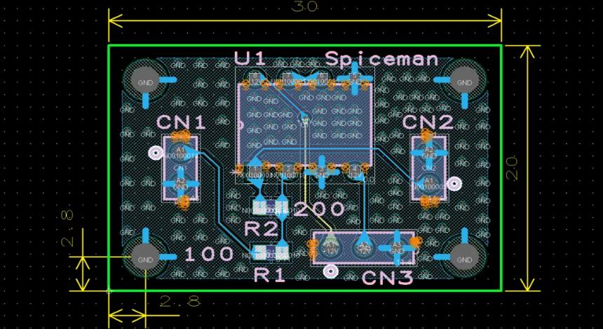
Microphone arrays, camera modules, the main processor, wireless radios, the display driver and power management all exchange data during a single interaction. The board carries the traffic between them, which makes interconnect density and signal integrity a product feature rather than an engineering detail.
Why Rigid Boards Do Not Fit
A conventional rigid board assumes a flat panel and a reasonably large enclosure. Glasses offer neither. The temples curve, the front frame curves, and the space available changes from one end of the product to the other, so no single flat shape can reach every module.
The alternative is to treat the frame itself as the interconnect route. Modules stay where they physically belong, and the board travels between them along the available geometry. That approach saves weight, removes connectors and reduces the assembly steps needed to build the product.
Flex Along the Frame
Flexible circuits follow curves without a connector at every bend, which suits a temple that folds and a frame that must stay thin. Coverlay thickness, conductor direction and bend radius all influence how the part survives repeated folding over the life of the product.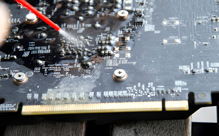
Manufacturing difficulty rises with every millimetre saved. Thin adhesiveless laminate is harder to handle, fine lines are more sensitive to etch variation, and the covering film must protect the circuit without stiffening the bend zone. Experience with flexible circuit assembly shows up in the yield of these parts.
Rigid Flex Reduces Connectors
Where a processor or a connector needs mechanical support, a rigid section is unavoidable. A rigid flex construction places that rigid area and the flexible connection in the same board, so the assembly no longer needs a separate cable and the two connectors that would have terminated it.
Each connector removed is a reliability improvement and a cost saving at the same time. The trade off is process difficulty: the bond between flexible and rigid layers, the registration between them and the handling of a panel with mixed thickness sections all demand careful control.
Micro HDI Solves the Fan Out Problem
Within the rigid sections, the component count keeps rising while the available area does not. Fine pitch packages and dense sensor interfaces consume routing space quickly, and ordinary through holes begin to block more area than they release when they pass through every layer of a thin board.
Microvia technology resolves that by allowing connections to travel only as far as they need to. Blind and buried structures free the routing channels, and the resulting HDI capability is what makes a modern wearable layout feasible without enlarging the frame.
Laser Vias and Fill Plating
Microvias are formed by laser, which means their quality depends on energy control, pad design and material behaviour. A via that is not fully filled leaves a void beneath the next layer, and a void that survives lamination may only reveal itself as an intermittent failure months later.
Plating thickness inside a small via is difficult to measure destructively without losing the sample, so routine control relies on cross sections from coupons and on electrical continuity structures placed in the panel. Both need to be part of the production routine rather than a one time study.
Assembly In a Very Small Space
Populating a wearable board is a different exercise from populating a server board. Solder paste volumes are smaller, placement tolerances are tighter, and the reflow profile has to suit a thin board that heats and cools faster than a rigid panel of the same area.
Camera modules, microphones and display interfaces are also sensitive to mechanical stress, so handling and fixturing matter as much as the soldering process itself. A partner with SMT assembly experience in miniature products anticipates these constraints before the first production lot.
Inspection That Matches the Scale
Inspection methods designed for large boards do not always resolve the details that matter on a wearable. Paste volume on a fine pitch pad, the fillet on a micro component and the void content under a small package all sit near the limit of what standard equipment reports reliably.
The practical answer is layered inspection. Paste measurement feeds the printer, optical inspection catches placement errors, and X-ray checks the joints that cannot be seen. Combined with board level testing, that sequence catches defects while they are still cheap to correct.
Weight and Battery Life as Design Constraints
Every gram and every milliwatt competes with the features that make the product attractive. A board design that adds a stiffener for process convenience, or a connector for assembly convenience, takes weight away from the battery or the frame, and the customer feels that trade off immediately.
This is why wearable projects often accept tighter manufacturing tolerances to save a fraction of a millimetre. The decision is rational, but it only works if the supplier can hold those tolerances in volume rather than only on a prototype panel.
Iteration Speed During Prototyping
Wearable products change quickly, because the enclosure, the optics and the software all evolve together. A board revision may be driven by a hinge redesign rather than by an electrical requirement, and the fabrication cycle has to accommodate that without restarting the project.
Keeping fabrication and assembly with one partner shortens the loop between a layout change and a populated board that can be tested in the actual frame. That combination of manufacturing process and assembly under one roof is what makes rapid iteration practical.
Connectors Are the Weak Point
In a wearable, the largest components are often the connectors rather than the chips. Each one occupies space, adds a mating operation and introduces a mechanical joint that can fail after repeated folding. Reducing connector count is therefore an engineering objective rather than a purchasing preference.
Rigid flex constructions and longer flexible runs achieve that reduction, at the cost of stricter process control during lamination. The trade is usually worthwhile, because a continuous circuit has far fewer places where the product can fail once it is in a customer hands.
Coverlay and Stiffener Decisions
Coverlay protects conductors in the bending area while stiffeners support the sections that must stay rigid. Choosing where each one goes is a design decision with a manufacturing consequence, because a stiffener placed a few millimetres too close to a bend changes how that bend behaves.
Suppliers should review these decisions with the customer rather than accept the drawing as final. A small adjustment, verified by bend testing, often removes a reliability risk without changing the electrical performance of the design or the way it fits inside the frame.
Wireless Integration in a Metal Frame
Antennas for wireless communication need clear space, and glasses frames are increasingly made of metal for reasons of style and strength. Integrating radios into that environment requires cooperation between the antenna design, the mechanical structure and the board layout from the beginning.
The board layout contributes by keeping ground planes predictable and by keeping noisy digital routing away from antenna feeds. On a board this small the available separation is limited, so every millimetre of routing discipline has a measurable effect on link quality.
Prototype to Volume for Wearables
Wearable projects rarely follow a linear path from prototype to volume. Volumes are uncertain, the industrial design keeps changing, and a first production run may be a few thousand units rather than a few hundred thousand. Suppliers have to support that shape of demand.
That argues for a partner who can move between small and large batches without changing factories or quality systems. Continuity of process between the prototype and the production lot is what keeps the performance measured in the laboratory valid in the shipped product.
Where the Value Concentrates
If smart glasses continue to gain capability without gaining weight, the manufacturing value will concentrate in flexible circuits, rigid flex constructions, microvia boards and miniature assemblies. Those are the parts of the product where capability cannot be substituted by ordinary capacity.
For suppliers, that is a demanding position to occupy, because it rewards process discipline over scale. For buyers, it means the choice of manufacturing partner influences what the product can be, not merely how much it costs to produce.