Millimeter Wave Radar PCB Manufacturing at 77GHz
When a radar chip reaches volume production with eight transmit and eight receive channels, the antenna board behind it stops being a supporting component and becomes part of the sensor itself. A millimeter wave radar PCB operating near 77GHz is judged by the same specification as the silicon, because detection range and angular accuracy depend on both.
The reported specification of four hundred metres of detection distance is not achieved by the chip alone. It is achieved by a chip, an antenna array, a laminate and a fabrication process that all hold their tolerances closely enough that the system still recognises a weak return echo at the far end of its range.
From Range Finding to Four Dimensions
Earlier automotive radar measured distance and relative speed. Current designs add height and angle, which allows the sensor to separate a pedestrian standing beside a guardrail from the guardrail itself. That extra information comes from more channels working at once, and each channel needs its own antenna element and feed network.
The board therefore grows more complicated before it grows any larger. More transmit and receive paths mean more transmission lines running close to one another, and the isolation between them becomes a routing problem as much as a circuit design problem.
Why the Wavelength Sets the Tolerance
At 77GHz the signal wavelength in the laminate is only a few millimetres, so a variation of a tenth of a millimetre represents a meaningful fraction of a wavelength. Conductor width, dielectric thickness and copper surface roughness all shift phase and insertion loss in ways that a digital board would never notice.
This is why manufacturing tolerances are quoted in absolute terms on radar boards. A process window that is perfectly acceptable on a controller board can be too wide for an antenna array, even though both boards are built in the same factory from similar materials.
Material Loss Decides Detection Distance
Every centimetre of laminate removes a small amount of the signal, and dielectric loss grows quickly with frequency. When a design aims at a longer detection range, the system must resolve a weaker echo, so the loss budget available to the board becomes narrower rather than wider. Material choice therefore sets an upper limit on performance.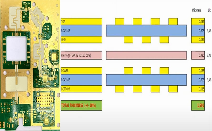
Low loss laminate, stable dielectric constant and consistent copper foil treatment are the properties that matter. A supplier with genuine low loss material capability can advise on which of those properties is worth paying for in a given design, rather than simply quoting a premium grade.
Antenna Arrays Multiply the Problem
A patch antenna array is a set of resonators, and resonators respond to geometry with an accuracy that ordinary circuit patterns do not require. If one element in the array is a few percent wider than its neighbours, its resonant frequency shifts and the beam pattern changes slightly.
Across eight transmit and eight receive paths, those small shifts accumulate. Beam steering relies on predictable phase relationships, so uniformity across the whole antenna region matters more than the accuracy of any single element, and that uniformity is created by the etching process.
Impedance Control Across a Panel
Feed lines to the antenna array must hold their characteristic impedance, and they must hold it consistently from one end of the panel to the other. Etch compensation, copper thickness variation and plating distribution all influence the result, and the influence is strongest on fine geometries.
Buyers should ask how impedance is verified: at which frequency, on how many coupons per panel, and against which acceptance window. A factory that reports a single nominal value is describing an intention, while one that reports a distribution is describing a process.
Lamination Thickness Is an Electrical Parameter
On most boards, dielectric thickness is a mechanical detail. On a radar board it is part of the electrical design, because the distance between a conductor and its reference plane sets the impedance directly. Prepreg flow during lamination therefore becomes a performance variable rather than a cosmetic one.
That is why stack up and layout decisions should be reviewed with the fabricator before release. Balanced construction, realistic copper distribution and a defined prepreg sequence reduce thickness variation, which in turn narrows the impedance spread across the panel.
The Satellite Architecture and Its Data Path
Satellite radar architecture moves processing away from the sensor and toward a central controller, which means the module now transmits a much richer data stream. Camera style interfaces and high speed serial links are replacing simple target outputs, and the volume of that traffic keeps rising as resolution improves.
The consequence reaches beyond the sensor board. Central computing platforms need high layer count boards with dense differential routing, while the link between sensor and controller needs its own controlled impedance path. One radar generation therefore pulls demand across several board types at once.
Two Board Families From One Sensor
A radar module contains at least two very different boards. The antenna board is a radio frequency design built on low loss material with tight geometry control, while the signal processing board resembles a dense digital product with ball grid arrays and high speed interfaces.
Factories that excel at one of those do not automatically excel at the other. A partner able to produce both, and to keep the process control records for both inside one system, removes a coordination problem from the customer side of the project.
Automotive Reliability on Top of RF Performance
Automotive qualification adds a second requirement that has nothing to do with radio performance. Components and boards must survive repeated thermal cycling, continuous vibration, humidity and the electrical noise of a vehicle, and they must do so for the life of the car rather than for the life of a warranty period.
For a high frequency board the combination is difficult, because the materials chosen for low loss are not always the materials chosen for mechanical stability. Dimensional stability under temperature change, copper to laminate adhesion and solder joint integrity all need to be validated together, not separately.
Batch Consistency Is the Real Qualification
A prototype that meets a radar specification proves very little. The qualification that matters is whether a thousandth panel meets the same specification without special attention, and whether the data that proves it exists for each lot that ships to the customer assembly line.
This is where board level testing and fabrication data come together. Line width, impedance, thickness and plating measurements from production, linked to the panels they came from, allow a supplier to answer a customer question with evidence rather than reassurance.
Grounding and Shielding on a Radar Board
Radio frequency design lives or dies by its ground. The reference plane has to behave as a plane rather than as a collection of islands, and every discontinuity, whether a slot, a via anti pad or a layer change, becomes a place where energy escapes or returns along an unintended path.
Manufacturing supports that by keeping the plane continuous and by controlling copper distribution across the panel. Etch compensation that preserves thin plane necks, and lamination that does not distort the stack, protect the electrical assumption the designer made before the layout was released.
Thermal Behaviour of an Antenna Module
A radar module sits behind a bumper, inside a sealed housing, with almost no airflow and exposure to direct sunlight. Its own electronics add heat on top of that. The laminate therefore sees temperature swings that shift dimensions, and a dimensional shift alters the resonant behaviour of the array.
Material selection and mechanical design share the responsibility. A laminate with a low coefficient of thermal expansion helps the antenna keep its tuning, while balanced copper in the stack keeps the panel flat enough for repeatable assembly and consistent thickness after pressing.
Handling Thin, High Frequency Material
Low loss laminates are often supplied as thin cores with a relatively soft resin system, which makes them harder to handle than standard FR-4. Panel distortion, edge damage and surface contamination all appear more easily, and each of those turns into yield loss on expensive material.
Practical control includes dedicated handling routes, careful baking schedules and drilling parameters tuned to the laminate rather than inherited from another product family. Factories that run these materials regularly already own the recipes, while factories that run them occasionally are still learning them.
Software Defined Radar and the Digital Board
As sensing moves toward centralised processing, more of the system becomes software and more of the silicon sits on the controller board. Board demand shifts toward dense digital designs with high speed serial links, where impedance and loss control matter for signal integrity rather than for radio performance.
Even so, the two requirements look very similar inside a factory. Both need controlled impedance, both need clean drilling and both need tight registration. A supplier with one process that serves both cases avoids the inefficiency of maintaining two separate quality regimes.
What to Ask an RF Board Supplier
Useful questions are specific. Which high frequency materials are stocked, and how long do they take to obtain? How is etch compensation applied to fine lines? What is the measured impedance spread, and is it recorded per panel? Which inspection steps run on every lot rather than on samples?
The answers reveal whether the factory treats radio frequency work as a normal extension of its manufacturing process or as an exception that only a few engineers understand. In this segment, the difference between those two positions decides whether a programme ramps smoothly.