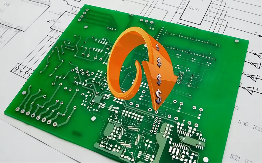
PCB Cost Factors: PCB Design, PCB Manufacturing & Cost Reduction Guide
As electronic products become smaller, faster, and more sophisticated, controlling printed circuit board (PCB) costs has become increasingly important. Modern electronic devices often require high-speed signals, compact layouts, higher component density, improved thermal performance, and increasingly complex manufacturing processes.
For engineering and purchasing teams, PCB cost is not determined by a single factor. It is influenced by the board’s dimensions, layer count, materials, copper thickness, surface finish, via technology, tolerances, manufacturing requirements, component selection, order volume, testing, and assembly requirements.
Understanding these cost drivers during the PCB Design stage can help engineers avoid unnecessary manufacturing expenses while maintaining the required electrical, mechanical, thermal, and reliability performance.
This guide explains the major factors that affect PCB pricing and provides practical strategies for reducing PCB costs without compromising product quality.
Key Factors That Increase PCB Costs
After completing a PCB layout and sending manufacturing data to a supplier, engineers often focus on the basic quotation parameters, such as board dimensions, layer count, copper thickness, and quantity.
However, the actual cost of a PCB can be influenced by many additional factors.
1. PCB Size and Shape
PCB dimensions have a direct influence on material utilization and manufacturing efficiency.
A larger PCB generally consumes more laminate, copper, solder mask, and other manufacturing materials. It may also reduce the number of boards that can be efficiently arranged on a production panel.
Board shape is equally important.
Standard rectangular or square PCBs are generally easier to panelize and manufacture. Irregularly shaped boards may create additional material waste and require more complex routing or milling.
For example, a PCB with large internal cutouts or unusual contours may result in lower panel utilization.
During PCB Design, engineers should therefore consider:
- Board dimensions
- Board outline
- Cutouts
- Mounting holes
- Edge requirements
- Panelization
- Array utilization
Optimizing the board outline can reduce material waste without changing the electrical functionality of the design.
2. Board Complexity
PCB complexity is another major cost driver.
A simple two-layer PCB generally requires fewer manufacturing steps than a high-density multilayer PCB.
As complexity increases, manufacturers may need additional processes such as:
- Sequential lamination
- Laser drilling
- Microvia formation
- Via filling
- Backdrilling
- Controlled-impedance fabrication
- Fine-line imaging
- Advanced surface finishes
- Additional inspection
HDI PCB technology is a good example. HDI boards typically use finer traces, smaller vias, microvias, and higher routing density than conventional multilayer boards.
These technologies can increase manufacturing costs, but they may be necessary when the product requires a small form factor and high interconnection density.
The goal should not be to minimize complexity at all costs. Instead, engineers should use only the complexity required by the electrical and mechanical requirements.
3. PCB Type

The PCB structure also affects manufacturing cost.
Common PCB categories include:
- Rigid PCB
- Flexible PCB
- Rigid-flex PCB
Rigid PCBs are generally the most widely used and can often be manufactured using mature, standardized processes.
Flexible PCBs use flexible dielectric materials such as polyimide and require different fabrication processes. They are useful when the circuit must bend, fold, or fit into limited spaces.
Rigid-flex PCBs combine rigid and flexible sections and can reduce system-level connectors and wiring in some applications. However, their manufacturing process is more complex, so they generally require a higher manufacturing budget.
Therefore, the PCB type should be selected according to the actual mechanical and electrical requirements rather than simply choosing the least expensive structure.
4. Substrate and Material Selection
PCB materials can have a significant effect on total cost.
FR-4 is widely used because it provides a practical balance of electrical performance, mechanical strength, thermal stability, manufacturability, and cost.
However, not every application should use standard FR-4.
Specialized applications may require:
- High-Tg laminates
- Low-loss laminates
- High-frequency materials
- Flexible materials
- Metal-core materials
- Ceramic substrates
- High-thermal-conductivity materials
For high-speed or RF applications, material selection can influence:
- Dielectric constant (Dk)
- Dissipation factor (Df)
- Signal propagation
- Insertion loss
- Impedance stability
- Thermal performance
Using a more expensive material does not automatically make a PCB better. The material should be selected based on actual electrical, thermal, mechanical, and reliability requirements.
A suitable material can improve performance while preventing unnecessary material costs.
5. Number of PCB Layers
Layer count is one of the most visible factors in PCB pricing.
A single-layer or double-layer PCB is generally simpler to fabricate than a multilayer PCB.
As the number of layers increases, manufacturers need additional:
- Core materials
- Prepreg
- Copper layers
- Lamination processes
- Registration control
- Drilling operations
- Inspection
However, it is not accurate to assume that every additional layer produces a fixed percentage increase in cost.
The actual cost depends on the entire stackup and manufacturing process.
For example, increasing a board from four layers to six layers may have a noticeable cost impact, while moving from a complex 12-layer design to a 14-layer design may involve a different cost structure depending on materials, copper weights, impedance requirements, and fabrication technology.
Therefore, layer count should be optimized according to routing density, power distribution, signal integrity, EMI/EMC, thermal requirements, and mechanical constraints.
6. Copper Thickness
Copper thickness is another important PCB cost factor.
Standard signal layers often use relatively thin copper, while power layers and high-current circuits may require heavier copper.
Increasing copper thickness can improve current-carrying capability and thermal performance, but it can also increase:
- Material cost
- Etching difficulty
- Minimum trace-width requirements
- Minimum spacing requirements
- Plating requirements
- Manufacturing complexity
For example, 1 oz copper is commonly used in many PCB applications, but heavier copper may be required for power electronics.
The correct copper thickness should therefore be determined from current requirements, allowable temperature rise, trace geometry, voltage drop, thermal design, and manufacturing capability.
Engineers should avoid specifying unnecessarily heavy copper because it can increase cost without providing a meaningful system-level benefit.
7. PCB Surface Finish
Surface finish protects exposed copper and provides the required solderability for assembly.
Common PCB surface finishes include:
HASL
Hot Air Solder Leveling is widely used and is generally economical.
Lead-free HASL is commonly selected when lead-free manufacturing requirements apply.
OSP
Organic Solderability Preservative provides a thin protective coating over exposed copper.
It can be cost-effective for appropriate applications but requires careful control of storage and assembly conditions.
ENIG
Electroless Nickel Immersion Gold provides a relatively flat surface and is widely used for fine-pitch components and applications requiring good surface uniformity.
It generally costs more than basic HASL.
Immersion Tin
Immersion tin provides a relatively flat solderable surface and can be suitable for fine-pitch applications, although storage and handling requirements must be considered.
ENEPIG
Electroless Nickel Electroless Palladium Immersion Gold provides a high-performance surface finish for demanding applications, but it generally carries a higher cost.
The correct surface finish should be selected based on:
- Component pitch
- Assembly process
- Shelf life
- Reliability requirements
- Environmental requirements
- Cost target
Choosing the least expensive finish is not always the best cost-saving strategy if it creates assembly or reliability problems later.
8. Finished Board Thickness
PCB thickness also affects material usage and manufacturing cost.
Common rigid PCB thicknesses vary according to the application and manufacturer’s standard capabilities.
Thicker boards may be required for:
- Mechanical strength
- Heavy components
- Backplane applications
- High-current applications
- Connector requirements
- Thermal or structural reasons
However, PCB thickness should not be increased simply because the circuit handles higher power.
Electrical power handling depends on several factors, including copper thickness, trace width, thermal management, board construction, and operating conditions.
Using the minimum practical finished thickness that satisfies mechanical and electrical requirements can help control cost.
9. Trace Width and Spacing
Trace width affects both PCB performance and manufacturing difficulty.
High-current circuits generally require wider traces or larger copper areas to control resistance and temperature rise.
At the same time, very narrow traces and tight spacing can increase manufacturing complexity.
Fine-line PCB designs may require:
- Advanced imaging
- Tighter process control
- Higher-resolution inspection
- Specialized materials or processes
Therefore, engineers should avoid unnecessarily aggressive trace and spacing rules.
A practical design should use the largest trace width and spacing that the electrical requirements permit.
This approach generally improves manufacturability and can increase production yield.
10. Production Quantity and Lead Time
Order quantity can strongly affect the unit price of a PCB.
Higher-volume production can allow manufacturing costs to be distributed across a larger number of boards and can improve panel utilization and production efficiency.
However, ordering excessive quantities simply to obtain a lower unit price may create inventory risk.
Lead time can also influence cost.
Expedited production may require:
- Priority scheduling
- Overtime
- Expedited material procurement
- Faster logistics
Therefore, engineers and purchasing teams should balance unit price against inventory, lead time, and project requirements.
11. Custom Manufacturing Requirements
Special manufacturing requirements can increase PCB costs.
Examples include:
- Non-standard hole sizes
- Unusual board shapes
- Tight dimensional tolerances
- Controlled impedance
- Special copper weights
- Advanced surface finishes
- High-temperature materials
- Conformal coating
- Waterproof or environmental protection
- Additional ICT
- Functional testing
- Custom test fixtures
- Special packaging
- Detailed inspection reports
Custom requirements can be completely justified when the application demands them.
However, unnecessary customization increases both manufacturing complexity and quotation cost.
Engineers should therefore distinguish between required specifications and preferred specifications.
How to Reduce PCB Manufacturing Costs
Cost reduction should begin during PCB Design, not after the manufacturing quotation has already been received.
The following strategies can help reduce unnecessary PCB expenses.
1. Optimize Board Space
Efficient component placement can reduce PCB dimensions and sometimes reduce the required layer count.
Important considerations include:
- Place connectors near appropriate board edges.
- Group related components together.
- Keep high-speed signal paths short where practical.
- Minimize unnecessary routing transitions.
- Maintain appropriate component clearances.
- Use available board space efficiently.
However, PCB density should not be increased blindly.
Overly dense layouts can make assembly, inspection, repair, and thermal management more difficult.
The goal is to achieve an appropriate balance between compactness and manufacturability.
2. Use Standard Component Packages
Standard component packages can simplify both PCB design and assembly.
Common SMT packages are usually easier to source and assemble than unusual or obsolete packages.
Standard packages may also provide:
- Better component availability
- More supplier options
- Easier stencil design
- More predictable assembly
- Lower procurement risk
However, package selection should still be based on electrical, thermal, mechanical, and reliability requirements.
3. Use Commonly Available Components
Component selection can have a significant effect on the overall product cost.
Whenever possible, engineers should consider components that are:
- Widely available
- Supported by multiple distributors
- In active production
- Available from approved suppliers
- Available in standard packages
Using commonly available components can reduce procurement lead times and simplify replacement strategies.
It is also important to consider the total cost of ownership rather than simply the unit price.
A very cheap component that frequently becomes unavailable may create greater long-term costs than a slightly more expensive but stable component.
4. Build and Test Prototypes Efficiently
Prototype testing should be structured around clearly defined engineering objectives.
A development laboratory can use tools such as:
- Oscilloscopes
- Digital multimeters
- Logic analyzers
- Power supplies
- Electronic loads
- Signal generators
- Thermal cameras
Early testing can identify design problems before large-scale production.
However, prototype PCB fabrication should generally be performed by a qualified PCB manufacturer rather than attempting to move industrial PCB manufacturing equipment into a development laboratory.
A better approach is to optimize the prototype process through:
- Rapid-turn PCB fabrication
- Local or strategically located suppliers
- Efficient shipping
- Consolidated orders
- Fast engineering feedback
- Reusable test fixtures
This can reduce development time and unnecessary logistics costs.
5. Apply DFM Rules During PCB Design
Design for Manufacturing (DFM) is one of the most effective ways to prevent unnecessary PCB manufacturing costs.
DFM considerations include:
- Minimum trace width
- Minimum spacing
- Hole diameter
- Aspect ratio
- Copper balance
- Board-edge clearance
- Solder-mask clearance
- Component spacing
- Via selection
- Panelization
- Surface finish
- Stackup construction
A design that follows the manufacturer’s standard capabilities is generally easier and more predictable to manufacture.
DFM should therefore be performed before the design is released for fabrication.
6. Optimize the PCB Stackup
The PCB stackup should be designed around actual electrical and manufacturing requirements.
A well-optimized stackup can help control:
- Layer count
- Impedance
- Crosstalk
- Signal integrity
- Power integrity
- Material consumption
- Lamination complexity
For high-speed designs, reducing layer count at the expense of signal integrity is not necessarily a cost-saving decision.
The correct strategy is to find the lowest-complexity stackup that still satisfies the electrical requirements.
7. Avoid Unnecessary Via Complexity
Vias can have a significant effect on manufacturing cost.
Standard through-hole vias are generally simpler than advanced structures such as:
- Blind vias
- Buried vias
- Microvias
- Stacked microvias
- Via-in-pad
- Filled and capped vias
Advanced via structures can be essential for HDI and high-density applications, but they should not be specified unless the design requires them.
When conventional through vias can satisfy the routing requirements, they may provide a simpler manufacturing solution.
8. Balance Performance and Cost
The cheapest PCB is not necessarily the most economical PCB.
For example, selecting a low-cost material that produces unacceptable signal loss may require additional redesign work.
Likewise, reducing copper thickness too aggressively may cause excessive temperature rise or voltage drop.
A better approach is to optimize the entire product cost.
Consider:
PCB Cost + Assembly Cost + Testing Cost + Logistics Cost + Rework Cost + Reliability Risk
This broader perspective can prevent short-term cost reductions from creating higher downstream expenses.
PCB Cost Optimization Checklist
Before sending a PCB design to manufacturing, engineers can review the following checklist:
- Is the board size optimized?
- Can the board outline be simplified?
- Is the layer count necessary?
- Is the selected material appropriate?
- Is copper thickness justified?
- Are trace widths unnecessarily small?
- Are clearances unnecessarily tight?
- Are advanced vias actually required?
- Is the surface finish appropriate?
- Can standard components be used?
- Are components readily available?
- Is the stackup manufacturable?
- Has DFM been completed?
- Has DFT been considered?
- Is panelization optimized?
- Is the production quantity appropriate?
- Are special inspection requirements necessary?
- Are testing and assembly costs included?
This review can identify cost drivers before the manufacturing quotation becomes fixed.
Hidden Costs to Consider
The quoted bare-board price does not always represent the total cost of an electronic product.
Additional expenses may include:
- Component procurement
- PCB assembly
- Stencil fabrication
- Test fixtures
- ICT
- Functional testing
- X-ray inspection
- Engineering charges
- Tooling
- Packaging
- Shipping
- Customs or logistics
- Rework
- Scrap
- Certification and compliance testing
Therefore, purchasing teams should evaluate the total landed cost rather than comparing PCB unit prices alone.
Working With PCB Manufacturers
Communication with the PCB manufacturer is an important part of cost optimization.
Before placing an order, engineers and purchasing teams should confirm:
- PCB material
- Finished thickness
- Copper thickness
- Layer count
- Surface finish
- Minimum trace and spacing
- Minimum hole size
- Impedance requirements
- Board dimensions
- Quantity
- Lead time
- Testing requirements
- Inspection requirements
- Packaging
- Shipping
It is also useful to communicate expected future production volumes.
If a prototype is expected to transition into high-volume production, the manufacturer can potentially recommend a more scalable manufacturing process from the beginning.
Kingda can provide PCB manufacturing and assembly support for projects requiring different materials, layer counts, copper weights, surface finishes, testing requirements, and production volumes.
Conclusion
PCB cost is influenced by much more than board size and quantity.
During PCB Design, engineers should consider layer count, material selection, copper thickness, board geometry, trace width, via technology, surface finish, component selection, DFM, DFT, and manufacturing tolerances.
The most effective cost-reduction strategy is not to remove every expensive feature. Instead, engineers should identify which specifications are genuinely required and eliminate unnecessary complexity.
A practical approach is to:
- Define electrical and mechanical requirements.
- Select the appropriate PCB material.
- Optimize board dimensions.
- Minimize unnecessary layer count.
- Use practical trace and spacing rules.
- Avoid unnecessary advanced via structures.
- Select appropriate copper thickness.
- Use standard components where possible.
- Apply DFM and DFT early.
- Optimize panelization and production quantity.
- Compare total manufacturing and assembly costs.
- Communicate requirements clearly with the PCB manufacturer.
By integrating cost considerations into the earliest stages of PCB Design and maintaining close communication throughout PCB Manufacturing, engineering teams can achieve a better balance between price, performance, reliability, and manufacturability.
Article Summary
PCB pricing is determined by a combination of design, material, manufacturing, assembly, testing, and logistics factors. Board size, shape, layer count, PCB type, material, copper thickness, finished thickness, trace geometry, surface finish, via technology, production quantity, and customization requirements can all influence the final cost.
The most effective way to reduce PCB costs is to optimize the design before production begins. Using standard materials and components, simplifying the board structure, optimizing the stackup, applying DFM/DFT principles, avoiding unnecessary manufacturing complexity, and planning production quantities carefully can reduce unnecessary expenses while maintaining required performance.
Ultimately, successful PCB cost optimization is about finding the right balance between PCB Design, PCB Manufacturing, quality, reliability, performance, and total product cost rather than simply selecting the lowest PCB quotation.