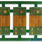
AI Hardware PCB Design: Power, Memory and High-Speed Interfaces
Boards that run inference or training workloads are built around a small number of extremely demanding components. An AI accelerator, its memory and its power delivery network together set requirements that dominate the layout, and everything else on the board has to fit around them. Designing an AI hardware PCB is mostly a matter of solving three problems: power, memory bandwidth and thermal removal.
What the Board Has to Carry
The compute element may be a graphics processor, a tensor processor, a field-programmable gate array or a dedicated neural processor. Whatever the architecture, it presents the same interface challenges: hundreds or thousands of connections at fine pitch, several high-bandwidth memory channels and a supply that draws tens or hundreds of amps at a low voltage.
Supporting components follow from that. High-speed volatile memory caches activations and weights, non-volatile storage holds the model, a power management section supplies the rails, and analogue front ends convert sensor data where the application involves imaging or audio. Communication interfaces such as PCI Express, USB and Ethernet connect the board to the rest of the system.
Stackup and Layer Planning
An HDI stackup is almost always required. Sixteen or more layers are common on accelerator boards, with microvias and via-in-pad structures used to escape the fine-pitch packages. The stackup is planned around three functions: dedicated ground and power planes, routing layers for the memory buses, and enough separation to keep the switching supply away from the sensitive interfaces.
The HDI stackup also determines what is achievable electrically. Microvia structures, dielectric thicknesses and the number of sequential lamination cycles all constrain the trace geometry, so the via strategy and the impedance targets have to be decided together rather than sequentially.
Power Integrity
Power delivery is usually the hardest problem on the board. A core rail drawing a hundred amps at under a volt has a tolerance window measured in tens of millivolts, and the current changes faster than any regulator can respond. The load transient is supplied by the decoupling network, so its impedance across frequency is what actually determines whether the rail stays inside tolerance.
power integrity design therefore starts with a target impedance rather than with a capacitor count. Local ceramic capacitors cover the highest frequencies, bulk capacitance handles the mid-range, and the plane structure provides the low-frequency path. Splitting the power plane into islands per rail keeps noise from one domain out of another, and the return path has to be continuous for every one of them.
Memory Routing
Memory bandwidth is the second constraint, and it is met by routing, not by part selection alone. High-bandwidth memory stacks sit close to the processor on an interposer or a very short channel, while discrete memory devices demand length-matched groups, matched differential strobes and identical via counts within each byte lane.
The routing has to be planned with the stackup rather than after it. Every layer transition introduces an impedance discontinuity and a stub, so the memory channel is normally routed on as few layers as possible and referenced to a solid plane throughout. For further detail on the channel rules, see the notes on high-frequency traces and data buses.
Thermal Design
Removing heat is the third constraint and often the one that determines the mechanical design. A dense accelerator dissipates its power through a small area, so a thermal via array under the die is the starting point rather than the whole solution.
Thermal vias connect the component pad to internal copper and to the opposite side of the board, where a spreader or a heat sink takes over. The effectiveness depends on the copper area the vias land on, not only on their number, and on the interface material and mounting pressure between the board and the cooling hardware. On a large accelerator, air cooling is often insufficient and the board has to be designed for a cold plate from the beginning.
High-Speed Interfaces
External interfaces bring their own constraints. PCI Express lanes are differential pairs with strict impedance and length requirements, and their connectors must be placed so that the routing to the processor is as direct as the mechanical design allows. Ethernet, USB and display interfaces follow similar patterns.
All of them share one rule: the reference plane beneath the pair must be continuous, and any required transition between layers needs a return via adjacent to the signal via. Interrupting that return path is the most common cause of a link that trains intermittently rather than failing outright, which is the hardest class of problem to debug.
Electromagnetic Compatibility
Fast interfaces and switching supplies make the board a significant source of emissions. The countermeasures are structural rather than additive: continuous planes, short return paths, controlled edge rates where the interface allows it, and connector shields bonded to the ground plane around the whole perimeter of the enclosure opening.
Filtering is added at the interfaces that leave the board, and shielding is used where a particular subsystem radiates above the limit. On a dense board the enclosure itself does part of the work, which is why the mechanical design and the layout should be developed together rather than in sequence.
The Design Flow
The sequence starts with the schematic and a placement plan driven by signal flow, then moves to the stackup and the via strategy, then to the critical routing. Power integrity and signal integrity simulations run in parallel with the layout rather than as a final check, because rework after routing is complete is expensive on a board of this density.
Manufacturability and testability reviews come next, covering the microvia structures against the fabricator capability and the test access against the probe strategy. It is worth closing those loops early, because an unreviewed HDI stackup is the most common reason an accelerator board misses its first fabrication cycle.
Where Impedance Control Becomes the Constraint
Every high-speed net on the board needs a defined impedance, and the tolerance is tighter than on an ordinary design because the interfaces have less margin. Impedance control therefore starts with the stackup: the dielectric thicknesses between each signal layer and its reference plane are chosen to produce a practical trace geometry at the target impedance.
That calculation has to be repeated for every layer that carries a critical net, because the same trace width produces a different impedance on a different layer. Where a net has to change layer, the width is adjusted at the transition and a return via is placed beside the signal via so that the reference path changes layer with it.
Verification follows the design. Impedance coupons fabricated on the same panel confirm that the produced geometry matches the calculation, and they remain the only practical way to know that the material and the process delivered the design intent.
FAQ
How many layers does an AI board need? Typically sixteen or more for a full accelerator, though a small edge inference module may fit on eight to twelve. The count is driven by the memory channels, the power domains and the reference plane requirements rather than by component count alone.
Is HDI always necessary? For large processors at fine pitch, in practice yes. The escape routing cannot be completed any other way, and the layer count that a through-hole-only construction would require is larger than an HDI equivalent.
What usually causes a first-pass failure? Power integrity margins and thermal performance, followed by memory channel signal integrity. All three are simulation problems that can be resolved on screen, which is why they should be modelled before fabrication rather than measured afterwards.