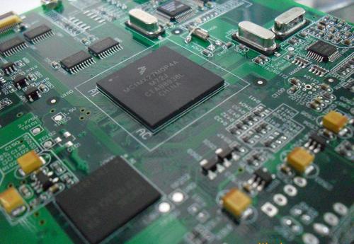
China has become one of the world’s major centers for Electronic Product Manufacturing, supported by a mature electronics supply chain, extensive manufacturing capabilities, and a large pool of engineering and production resources. Within this ecosystem, the PCB industry has developed rapidly to support increasingly diverse applications.
As electronic products continue to become smaller, lighter, more powerful, and more thermally demanding, different PCB technologies are required for different applications. Aluminum-based PCBs are widely used where efficient heat dissipation is important, while Flexible PCB technology provides mechanical flexibility and space-saving advantages.
Understanding the materials, structures, performance requirements, and design considerations of these PCB technologies is essential for achieving reliable products.
What Should Be Considered When Designing an Aluminum PCB?
An aluminum PCB, also known as a Metal Core PCB (MCPCB), is designed to provide both electrical interconnection and efficient thermal management.
Compared with conventional FR-4 boards, an aluminum-based PCB provides a metal core that can conduct heat away from heat-generating components. This makes it particularly suitable for LED lighting, power electronics, automotive electronics, industrial equipment, and other applications where thermal performance is critical.
Basic Structure of an Aluminum PCB
A typical aluminum Metal Core PCB consists of three primary functional layers:
- Conductive Layer
Usually made of copper, this layer contains the circuit traces, solder pads, and other electrical features. - Dielectric and Thermal Insulation Layer
This layer electrically isolates the copper circuit from the metal core while providing a thermal path for transferring heat toward the aluminum substrate. - Metal Base Layer
Usually made of aluminum, this layer provides mechanical support and serves as the primary heat-spreading structure.
The performance of an aluminum PCB depends heavily on the characteristics of the dielectric layer, particularly its thermal conductivity, electrical insulation capability, thickness, and long-term reliability.
Aluminum PCB Thermal Performance
Thermal management is one of the primary reasons for choosing an aluminum PCB.
For LED lighting and power electronics, heat generated by components must be efficiently transferred away from the active device. Excessive operating temperature can accelerate component aging, reduce efficiency, and negatively affect product reliability.
Important material properties include:
- Thermal conductivity
- Specific heat capacity
- Coefficient of thermal expansion
- Electrical conductivity
- Electrical resistivity
- Melting point
- Hardness
- Tensile strength
- Elastic modulus
- Fatigue strength
- Machinability
Among these properties, thermal conductivity is particularly important for applications with high heat-generation requirements.
However, the thermal conductivity of an aluminum-based PCB cannot be evaluated simply by looking at the aluminum core. The dielectric layer between the copper circuit and aluminum base also contributes significantly to the overall thermal resistance.
Therefore, designers should evaluate the complete thermal path:
Component → Copper Layer → Dielectric Layer → Aluminum Core → Heat Sink or Chassis
This complete thermal path is more meaningful than considering the thermal conductivity of the aluminum substrate alone.
Choosing the Right Aluminum PCB Material
Different manufacturing processes and material formulations can produce significantly different thermal performance.
When comparing aluminum PCB materials, designers should consider:
- Thermal conductivity of the dielectric layer
- Dielectric thickness
- Breakdown voltage
- Copper thickness
- Aluminum thickness
- Coefficient of thermal expansion
- Operating temperature
- Thermal resistance
- Mechanical strength
- Manufacturing cost
A higher thermal-conductivity dielectric generally improves heat transfer, but it may also affect material cost and other electrical or mechanical properties.
Therefore, material selection should be based on the actual thermal load and application requirements rather than simply choosing the highest available thermal conductivity.
For demanding thermal applications, engineers should request verified material specifications and third-party test data where appropriate.
Common PCB Layout Problems and Design Considerations
Successful product development requires more than achieving basic electrical functionality. A professional PCB Layout must also consider mechanical compatibility, thermal performance, electromagnetic compatibility, assembly, maintenance, and manufacturing.
The following questions should be addressed during the PCB design stage.
1. Mechanical Installation
Does the PCB need mounting edges, tooling holes, or special installation features?
Designers should reserve sufficient space for:
- Mounting holes
- Positioning holes
- Screws and fasteners
- Connectors
- Mechanical supports
- Board-to-board interfaces
The PCB outline must also match the enclosure and mechanical structure of the final product.
2. Component Spacing
Is the spacing between components sufficient?
Component placement should consider:
- Component body dimensions
- Component height
- Connector clearance
- Assembly equipment
- Rework requirements
- Thermal spacing
- Mechanical interference
Tall components and heat-generating devices should be carefully positioned to prevent conflicts with the enclosure or neighboring components.
3. Impedance and Signal Integrity
High-speed products require careful consideration of impedance and Signal Integrity.
Trace width, trace spacing, dielectric thickness, copper thickness, and reference-plane structure all influence controlled impedance.
Critical signals should have predictable return-current paths and should be routed away from strong noise sources whenever possible.
4. Power Integrity
Power-distribution stability is another important consideration.
The power network should provide low impedance and sufficient current capacity. Decoupling capacitors should be positioned close to the power pins of relevant ICs, while high-current paths should use sufficiently wide copper traces or copper planes.
5. Thermal Management
Heat-generating components should be positioned according to the overall thermal architecture.
Designers should consider the distance between:
- Power devices
- Heat sinks
- Aluminum substrates
- Thermal vias
- High-temperature components
- Temperature-sensitive components
On an aluminum Metal Core PCB, the thermal path should be designed from the component to the metal core and then toward the final heat-dissipation structure.
6. EMC and EMI Control
The overall PCB Design should also address electromagnetic compatibility.
Effective techniques include:
- Proper component partitioning
- Short high-speed traces
- Continuous ground planes
- Controlled return-current paths
- Appropriate decoupling
- Ground stitching
- Separation of noisy and sensitive circuits
- Controlled impedance
- Shielding where necessary
EMC should be considered during the initial layout rather than treated as a debugging step after the prototype is completed.
7. Serviceability and Maintenance
Components that require frequent replacement or adjustment should be easy to access.
Designers should consider whether:
- Replaceable components can be removed easily
- Test points are accessible
- Adjustable components can be calibrated
- Connectors can be serviced
- Heat-generating components can be inspected
Good serviceability can significantly reduce maintenance time and improve the overall lifecycle of the product.
Factors Affecting Flexible PCB Flexibility
Unlike aluminum-based PCBs, a Flexible PCB is designed to bend, fold, or move within a defined mechanical range.
The flexibility of a flexible circuit depends on several factors, including substrate material, copper type, copper thickness, dielectric thickness, adhesive structure, and overall stackup.
1. Copper Type
Copper foil can generally be divided into rolled-annealed (RA) copper and electrodeposited (ED) copper.
For applications involving repeated bending, RA copper is often preferred because of its mechanical characteristics and suitability for dynamic-flex applications.
The appropriate copper type should be selected according to the bending radius, bending frequency, and expected service life.
2. Copper Thickness
For the same material system, thinner copper generally provides greater flexibility.
However, reducing copper thickness also reduces current-carrying capacity and may affect electrical resistance and thermal performance.
Therefore, copper thickness should be selected by balancing mechanical flexibility with electrical requirements.
3. Dielectric and Adhesive Materials
The dielectric system has a significant influence on flexible-circuit performance.
Polyimide (PI) is widely used as a flexible substrate because it offers good thermal stability, electrical insulation, and mechanical flexibility.
The adhesive system can also affect the bending characteristics of the finished circuit. Adhesive thickness, modulus, and construction should be selected according to the application’s mechanical requirements.
For highly flexible applications, a thinner and mechanically compliant material stackup is generally preferred.
4. Polyimide Thickness
The thickness of the PI substrate directly affects the flexibility of the circuit.
A thinner PI layer generally allows a smaller bending radius and greater flexibility.
However, extremely thin materials may require additional handling and manufacturing controls. Therefore, substrate thickness should be selected according to the required bend radius, mechanical strength, environmental conditions, and manufacturing process.
Flexible PCB Design Guidelines
A reliable Flexible Circuit requires more than simply using flexible materials.
Designers should also consider the mechanical behavior of the circuit throughout its operating life.
Avoid Sharp Corners in Bend Areas
Sharp corners can concentrate mechanical stress and increase the risk of cracking or delamination.
Curved routing and rounded corners are generally preferable in areas subject to repeated bending.
Keep Vias and Components Away from Bend Zones
Components, vias, and rigid structures should generally be kept outside areas that experience repeated bending.
The transition between rigid and flexible sections should be designed carefully to prevent excessive mechanical stress.
Control the Bend Radius
The minimum bend radius should be determined according to the material stackup, copper thickness, number of layers, and whether the application involves static or dynamic bending.
Dynamic-flex applications generally require more conservative bending conditions than one-time or occasional folding.
Consider Copper Distribution
Uneven copper distribution can affect the mechanical behavior of a flexible circuit.
Where possible, copper should be distributed consistently, particularly in areas that experience repeated bending.
Designers should also avoid unnecessary copper concentration near the neutral bending axis unless required by the electrical design.
Aluminum PCB vs. Flexible PCB
Aluminum PCBs and flexible circuits solve very different engineering problems.
An aluminum Metal Core PCB is primarily selected for thermal management and mechanical support, while a Flexible PCB is selected for flexibility, space optimization, and three-dimensional interconnection.
| Feature | Aluminum PCB | Flexible PCB |
|---|---|---|
| Primary advantage | Thermal management | Mechanical flexibility |
| Typical substrate | Aluminum | Polyimide or similar flexible film |
| Typical applications | LED, power electronics, automotive | Wearables, cameras, displays, compact electronics |
| Thermal performance | Excellent heat spreading | Depends strongly on material and structure |
| Mechanical flexibility | Rigid | Flexible |
| Main design concern | Thermal resistance | Bend radius and mechanical reliability |
Selecting the appropriate PCB technology should therefore begin with the actual product requirements rather than simply comparing material costs.
Kingda PCB Manufacturing Support
Kingda supports PCB manufacturing requirements for a wide range of electronic applications, including conventional multilayer PCBs, high-performance boards, metal-core structures, and flexible circuit technologies.
For aluminum-based PCB projects, manufacturing considerations may include copper thickness, dielectric performance, aluminum thickness, thermal requirements, board dimensions, and mechanical processing.
For flexible circuit projects, important manufacturing factors include material selection, copper thickness, layer count, bend requirements, minimum feature size, registration accuracy, and flexible-to-rigid transition structures.
Kingda works with customers to align PCB Design, material selection, and manufacturing requirements before production. This approach helps reduce manufacturability risks and improves consistency between the PCB design and the final manufactured product.
Conclusion
Modern electronic products increasingly require PCB technologies that can meet demanding electrical, thermal, mechanical, and space constraints.
An aluminum Metal Core PCB provides an effective solution for applications where heat dissipation and mechanical stability are important. Its performance depends not only on the aluminum substrate but also on the dielectric thermal path, copper structure, component placement, and overall thermal design.
A Flexible PCB, by contrast, provides mechanical freedom and enables compact three-dimensional interconnections. Its flexibility is determined by the copper type and thickness, PI substrate, adhesive structure, layer count, and overall stackup.
Whether designing an aluminum PCB or a Flexible Circuit, engineers should consider electrical performance, thermal management, mechanical reliability, PCB Layout, and PCB Manufacturing requirements from the beginning.
By integrating these considerations into the design process and working closely with an experienced manufacturing partner such as Kingda, engineers can develop PCBs that are not only functional but also reliable, manufacturable, and optimized for real-world applications.