Aluminum PCB Substrate: Thermal Performance and Application Scope
An aluminum PCB substrate replaces the usual glass-reinforced epoxy with a metal base, typically a low-alloy aluminum sheet with a thin insulating dielectric layer bonded to it and the copper circuit formed on top. The construction exists for one reason: to move heat out of the circuit and into a metal structure that can spread and dissipate it. Where an FR-4 board would need external heat sinking, a metal-backed board handles the thermal path inside the board itself.
The trade is that the metal base is also the mechanical structure and the electrical ground reference if it is connected, so the design has to satisfy thermal, mechanical, and insulation requirements at the same time. That makes it a different design problem rather than simply a material substitution.
Why a Metal Base Improves Thermal Performance
The dielectric layer in a metal core board is thin, typically tens of microns, which puts the copper conductors very close to a large thermal mass. Heat that would otherwise spread laterally through the laminate and conduct slowly to the ambient now passes through a short vertical path into the aluminum, where it spreads across the whole board area and radiates or conducts to a heat sink or chassis.
Two consequences follow. The first is a lower operating temperature for the same power, which extends the life of the components and allows higher power density in the same volume. The second is a lower thermal conductivity path for heat spreading than laminate can provide, which means the board can be smaller for the same dissipation instead of relying on a large copper area on a conventional substrate.
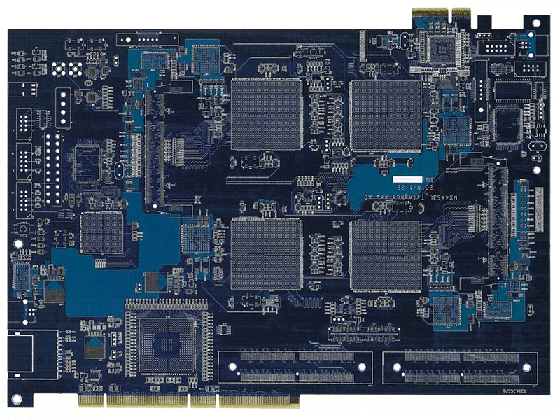
Where the heat must be moved aggressively, the metal base can also carry a heat sink directly, which removes the thermal interface between the board and the enclosure that would otherwise dominate the thermal resistance.
Electrical Insulation and Voltage Rating
The dielectric layer must isolate the circuit from the metal base, and its thickness determines the breakdown voltage of the assembly. A properly constructed board can withstand several thousand volts, which is why metal core constructions appear in power conversion and lighting products that operate at mains potential. The dielectric breakdown rating is a specification of the material and its thickness, and it should be verified rather than assumed: a thin dielectric that is adequate for a low-voltage driver is not adequate for a mains-connected supply.
Where the metal base is used as an electrical ground, that decision has to be made deliberately. Connecting the base to the circuit ground improves shielding and reduces common-mode noise, but it also means the base is at the circuit potential everywhere, including any exposed edge. Where the base must be isolated from the circuit, the mounting hardware has to maintain that isolation, and the design should include a creepage distance that reflects the working voltage.
Features That Follow From the Construction
Several characteristics distinguish a metal core board from a conventional one. Current capacity for a given trace width is higher, because the metal base absorbs the heat that the trace generates, so the same conductor can carry more current before reaching its temperature limit. Mechanical stiffness is much higher, which supports thin and large boards without warpage and allows heavier components to be mounted without a stiffener. The base also suppresses electromagnetic radiation, because the metal plane behind the circuit acts as a shield.
The limitations are equally characteristic. Aluminum expands more than the laminate used on a conventional board, so holes and surface-mount joints experience more mechanical stress over temperature, and the board is usually limited to a single layer for the circuit, often with a single routing layer plus the metal base. Machining the aluminum requires different tooling, and plated through-hole structures are more difficult because the base cannot be drilled and plated in the same way.
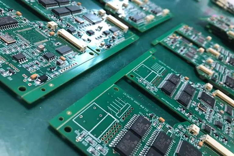
The practical result is that most metal-backed designs keep the routing simple and put the complexity in the copper area rather than in the layer count. Getting more routing into one layer often means accepting zero-ohm links or moving the circuit to a different topology.
Assembly on a Metal Backed Board
The SMT assembly process is compatible with metal core boards, and the thermal mass of the base changes the reflow profile substantially. The board absorbs heat much faster than an FR-4 panel of the same size, so the preheat and soak stages have to be shortened and the peak temperature controlled carefully. Where the board is large, the conveyor and support system has to handle significantly more weight.
Because the base is a large thermal mass, soldering a pad that is connected to a wide copper area can be difficult unless thermal relief is applied appropriately. The same property improves the thermal performance of the finished product, which is why the relief has to be designed to balance the two requirements rather than applied as a default pattern.
Applications
Audio equipment is a long-standing application, because the metal base provides both heat removal and shielding for the low-level stages of an amplifier. Power conversion is another, including switching regulators and converters, where the board itself acts as the heat sink for the switching devices. Communications equipment uses metal-backed boards for high-frequency amplifiers and filters where thermal stability affects the electrical performance.
Automotive electronics, motor drive circuits, and power modules such as solid-state relays and rectifier bridges all use the construction for the same reason: the power devices need a low thermal resistance path, and the board can provide it without an additional heat sink interface. Lighting products use the metal base as the mounting surface for the light source and as the thermal path simultaneously.
Handling and Storage
Metal core boards are more sensitive to storage conditions than conventional laminate. The exposed aluminum and the thin dielectric are prone to moisture uptake, discoloration, and surface oxidation, and a board that has absorbed moisture can blister during reflow.
The practical rule is to use the boards within a short period after opening the vacuum packaging, typically two days, and to bake them according to the supplier’s recommendation before soldering if they have been exposed longer. Boards should be stored in a dry, dark environment, and the surface should be inspected before assembly for any sign of oxidation or damage to the dielectric layer.
Designing the Thermal Path
The metal base makes the vertical path short, but the heat still has to be spread to the surfaces that actually lose it. Copper area on the circuit side, thermal vias where the layer structure allows them, and a defined path from the base to the enclosure all determine the final temperature. Current-carrying capacity should be calculated with the operating temperature in mind rather than at room temperature, using the method described in trace width and current calculation.
Where the board will be exposed to humidity or contamination, the metal base does not protect the circuit side, which still requires a coating. The options and their process requirements are covered in conformal coating and board protection and in potting and dispensing adhesives for PCB.
FAQ
Can a metal core board have more than one circuit layer? It can, but the second layer is usually the metal base acting as ground, and additional signal layers significantly complicate the construction and the cost. Most designs use one copper layer for the circuit and treat the aluminum as the thermal and mechanical structure.
Is plating through the aluminum base possible? Plated through-holes in a metal core board are difficult, because the aluminum cannot be plated directly and requires an insulating sleeve or a different construction. Designs that need through-hole connections usually use a different substrate or accept connectors and wire links instead.
Why does the reflow profile have to change? Because the metal base stores and conducts heat far more effectively than laminate. The board reaches temperature faster and holds it longer, so the profile has to be adjusted to avoid overheating the components while still forming good joints on the high thermal mass areas.