Automotive PCB vs. Standard PCB: 5 Key Differences You Need to Know
As electric vehicles (EVs) and advanced automotive electronics continue to develop, printed circuit boards have become increasingly important in systems such as battery management systems (BMS), motor controllers, onboard chargers, DC-DC converters, and vehicle control units.
Compared with PCBs used in conventional consumer electronics or office equipment, an Automotive PCB must operate reliably under significantly more demanding conditions. Automotive electronics can be exposed to wide temperature fluctuations, continuous vibration, electrical noise, moisture, chemicals, and high-power loads.
These requirements create substantial differences between automotive and standard PCBs in terms of materials, electrical design, reliability, quality control, and manufacturing processes.
Understanding these differences is essential when selecting a PCB manufacturer for an automotive or EV project.
1. Environmental Durability: Automotive PCBs Must Withstand Harsh Conditions
One of the biggest differences between an automotive circuit board and a standard PCB is environmental durability.
A consumer electronic device may operate primarily in a relatively controlled indoor environment. An automotive PCB, however, may be installed in an engine compartment, battery system, power electronics module, charging system, or other location exposed to significant environmental stress.
Wide Temperature Range
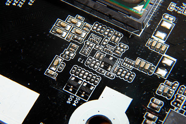
Automotive electronics can experience substantial temperature variations during vehicle operation, storage, charging, and exposure to outdoor conditions.
Depending on the installation location and application, an automotive PCB may need to withstand temperatures ranging from below freezing to well above normal room temperature. Power electronics located near batteries, motors, or other heat-generating components can face particularly demanding thermal conditions.
The PCB material, resin system, copper structure, solder mask, and assembly materials must therefore be selected to maintain mechanical and electrical stability throughout the expected operating temperature range.
Thermal cycling is also important. Repeated expansion and contraction can place stress on:
- Copper traces
- Plated through-holes
- Via structures
- Solder joints
- Layer-to-layer interfaces
- Component connections
Poorly controlled materials or manufacturing processes can eventually lead to cracks, delamination, or electrical failures.
Vibration and Mechanical Shock
Vehicles are continuously exposed to road vibration, mechanical shock, acceleration, and changes in mechanical loading.
For this reason, an Automotive Circuit Board must be designed and manufactured with sufficient mechanical robustness.
Important considerations may include:
- Strong interlayer bonding
- Appropriate board thickness
- Reliable plated through-holes
- Robust solder joints
- Proper component anchoring
- Mechanical support for large or heavy components
A PCB that performs well in a stationary electronic device may not necessarily provide the same reliability under continuous automotive vibration.
Moisture and Chemical Exposure
Automotive electronics may also encounter humidity, condensation, cooling fluids, oils, cleaning chemicals, and other environmental contaminants.
Depending on the application, additional protection such as conformal coating, appropriate solder mask selection, sealed enclosures, or specialized materials may be required.
For automotive applications, environmental protection should therefore be considered during both PCB design and manufacturing rather than treated as an afterthought.
For projects requiring professional production support, Gopcba provides comprehensive Automotive PCB Manufacturing solutions for different board structures and application requirements.
2. Electrical Performance: Higher Voltage, Current, and EMC Requirements
Automotive electronics increasingly combine high-power systems with sensitive digital and analog circuits.
Electric vehicles make this challenge even more significant because traction batteries and power conversion systems can operate at hundreds of volts, while certain power circuits may carry substantial current.
High-Voltage Insulation
High-voltage automotive systems require careful control of electrical clearance, creepage distance, dielectric materials, insulation systems, and PCB geometry.
For example, PCB designs used in battery management, charging, and power conversion systems may need to maintain sufficient separation between high-voltage and low-voltage circuits.
The exact requirements depend on system architecture, working voltage, pollution level, applicable safety standards, and enclosure design.
PCB manufacturers must be able to maintain the specified dimensions and tolerances consistently during production.
High-Current Capability
Power electronics can also require significantly greater current-carrying capability than many conventional consumer products.
Designers may use:
- Wider copper traces
- Larger copper areas
- Heavier copper
- Copper planes
- Multiple parallel current paths
- Thermal vias
- Appropriate thermal management structures
Simply increasing copper thickness is not always the best solution. Trace geometry, heat dissipation, component placement, layer structure, and current distribution should all be considered together.
Electromagnetic Compatibility
Automotive systems contain numerous electronic modules operating close to one another. At the same time, vehicles increasingly include radar, cameras, wireless communication, navigation, sensors, and high-speed data networks.
Consequently, EMC and signal integrity can be critical.
Automotive PCB design may require careful attention to:
- Ground planes
- Power distribution
- Return current paths
- Differential pairs
- Shielding
- Filtering
- Impedance control
- Separation between noisy and sensitive circuits
These considerations make automotive PCB design substantially more demanding than many standard PCB applications.
3. Safety and Quality Standards: Automotive Electronics Require Stronger Control
Automotive electronics are safety-critical in many applications. A failure in a vehicle control, battery, charging, or power management system can have consequences far beyond the malfunction of a typical consumer device.
Therefore, automotive electronics manufacturers generally operate under more rigorous quality and reliability requirements.
Automotive Environmental Testing
Standards such as ISO 16750 provide guidance for environmental conditions and testing of electrical and electronic equipment used in road vehicles. Depending on the application, testing may address factors such as temperature, mechanical loads, humidity, chemical exposure, and other environmental stresses.
However, the exact standards and tests applicable to a particular PCB depend on the vehicle system, customer specifications, component requirements, and final product architecture.
Component Qualification
Automotive projects may also involve component qualification frameworks such as AEC-Q100 for integrated circuits and AEC-Q200 for passive components.
It is important to distinguish component qualification from PCB manufacturing requirements. AEC-Q200, for example, is primarily associated with qualification of passive electronic components rather than serving as a general PCB manufacturing standard.
Therefore, automotive PCB suppliers should understand the customer’s complete quality requirements instead of simply treating an automotive project as a conventional PCB order.
Quality Management and Traceability
Automotive supply chains also place strong emphasis on process consistency and traceability.
Manufacturers supporting automotive programs may need robust quality management systems, controlled processes, inspection records, material traceability, process documentation, and corrective-action procedures.
This is particularly important when the same PCB must be manufactured repeatedly over a long production lifecycle.
4. Reliability: Automotive PCBs Must Support Long-Term Operation
Reliability is another major difference between automotive PCBs and standard electronic boards.
A vehicle is expected to operate for many years, often under repeated cycles of starting, driving, charging, heating, cooling, and vibration.
As a result, PCB reliability cannot be evaluated only by whether a newly manufactured board works correctly.
Long-Term Material Stability
The PCB substrate must maintain its mechanical and electrical properties throughout the expected operating life.
Important material characteristics may include:
- Thermal stability
- Glass transition temperature
- Decomposition resistance
- Moisture resistance
- Dielectric stability
- Copper adhesion
- Resistance to delamination
Material selection should be based on the actual temperature, voltage, frequency, and environmental requirements of the application.
Plated Through-Hole and Via Reliability
Plated through-holes and vias are particularly important in multilayer automotive PCBs.
Thermal cycling causes the PCB substrate and copper plating to expand and contract at different rates. Repeated stress can eventually affect plated hole integrity.
Manufacturing controls such as:
- Controlled hole drilling
- Proper desmear
- Consistent electroless copper deposition
- Controlled electroplating
- Appropriate copper thickness
- Lamination process control
can contribute to long-term reliability.
Solder Joint Reliability
Component solder joints are also exposed to thermal and mechanical stress.
Large components, connectors, power devices, and high-mass components can place additional mechanical loads on solder joints during vibration and thermal cycling.
For this reason, automotive PCB assembly requires careful consideration of component placement, pad design, soldering profiles, and mechanical support.
Gopcba also provides Mixed Technology PCB Assembly for designs combining SMT and through-hole components.
5. Manufacturing Requirements: Automotive PCBs Need More Process Control
The manufacturing process is another important difference between automotive and standard PCBs.
Automotive applications may require tighter process control, more detailed inspection, and stronger production traceability.
Controlled PCB Fabrication
The manufacturing process can involve strict control of:
- Layer alignment
- Board thickness
- Copper thickness
- Trace width and spacing
- Hole size
- Hole position
- Plating thickness
- Surface finish
- Impedance
- Dimensional tolerances
For complex automotive boards, even small manufacturing variations can affect electrical performance or long-term reliability.
Inspection and Testing
Depending on customer requirements and product criticality, automotive PCB production may incorporate multiple inspection methods, including:
- Automated Optical Inspection (AOI)
- Electrical testing
- Flying probe testing
- X-ray inspection
- Cross-section analysis
- Dimensional inspection
- Solderability testing
- Thermal cycling
- Environmental reliability testing
The appropriate testing program should be determined according to the PCB design, application risk, customer specifications, and applicable industry requirements.
It is not accurate to assume that every automotive PCB automatically requires every possible test. Instead, testing should be matched to the actual reliability objectives of the product.
Automotive PCB vs. Standard PCB: Quick Comparison
| Requirement | Automotive PCB | Standard PCB |
|---|---|---|
| Operating Environment | Wide temperature, vibration, moisture, chemicals | Usually more controlled |
| Electrical Requirements | May involve high voltage and high current | Often lower power |
| EMC Requirements | Typically more demanding | Depends on application |
| Mechanical Reliability | High resistance to vibration and shock | Application-dependent |
| Material Selection | Often requires higher-performance materials | Standard FR-4 may be sufficient |
| Quality Control | Strong process control and traceability | Depends on product requirements |
| Testing | More extensive reliability validation may be required | Usually based on application |
| Product Life | Often designed for long-term automotive service | Varies significantly |
| Manufacturing Complexity | Generally higher | Application-dependent |
How to Choose an Automotive PCB Manufacturer
Choosing an appropriate supplier is critical for automotive electronics projects.
Instead of evaluating a manufacturer only by price, purchasing teams and engineers should examine its technical capabilities and quality systems.
Check Material and Process Capabilities
Confirm whether the supplier can support the required:
- Automotive-grade or application-appropriate laminates
- Copper thickness
- Layer count
- Board thickness
- High-current structures
- Controlled impedance
- Fine-pitch features
- Via structures
- Surface finishes
Evaluate Reliability and Quality Control
Ask about manufacturing process controls, inspection methods, traceability, testing capabilities, and reliability validation.
A supplier that understands the relationship between material selection, PCB fabrication, assembly, and field reliability can provide much more value than a supplier focused solely on low unit pricing.
Consider PCB Assembly Capabilities
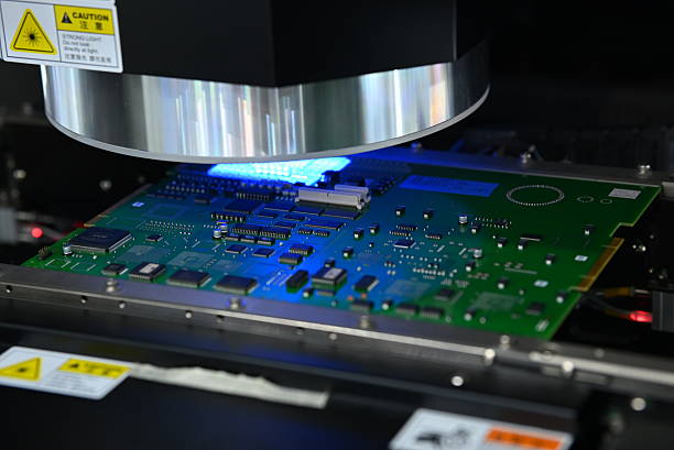
Automotive electronics often combine processors, sensors, power components, connectors, capacitors, resistors, and other components on the same assembly.
Integrating PCB fabrication with assembly can simplify supply-chain management and reduce communication issues.
For early-stage automotive development, Gopcba offers Prototype PCB Assembly to support design verification before larger-scale production.
For production programs that require both SMT and THT processes, an integrated assembly solution can also improve manufacturing coordination.
Why Automotive PCBs Cost More Than Standard PCBs
Automotive PCBs are generally more expensive not simply because they are used in vehicles, but because they often require higher performance, tighter process control, additional validation, and more demanding materials.
Cost can be affected by:
- High-performance laminate
- Increased copper thickness
- More PCB layers
- High-density routing
- Controlled impedance
- Advanced via structures
- Higher inspection requirements
- Reliability testing
- Specialized surface finishes
- Tighter manufacturing tolerances
- Longer quality documentation and traceability requirements
However, higher PCB cost should be evaluated against the total cost of product failure.
For automotive electronics, reliability problems discovered after mass production can result in much greater costs than investing in proper PCB design validation and manufacturing controls during development.
Conclusion
The differences between an Automotive PCB and a standard PCB are fundamentally driven by the operating environment, electrical requirements, safety considerations, reliability expectations, and manufacturing controls.
Automotive circuit boards may need to withstand temperature cycling, vibration, moisture, chemical exposure, high voltage, high current, and electromagnetic interference while maintaining reliable operation over a long service life.
For EV applications in particular, the increasing use of battery systems, motor drives, onboard chargers, power converters, sensors, and high-speed communication systems continues to raise PCB performance requirements.
The right approach is not simply to choose the most expensive PCB material or manufacturing process. Instead, engineers should define the actual electrical, thermal, mechanical, environmental, and reliability requirements first and then select materials, board structures, fabrication processes, and assembly technologies accordingly.
By working with an experienced PCB manufacturing and assembly partner, automotive electronics developers can reduce manufacturing risks, improve design validation, and establish a more reliable path from prototype to production.