BGA PCB Surface Finish Risks and How to Prevent Soldering Defects
As electronic products continue to become smaller, thinner, and more powerful, BGA assembly has become increasingly common in high-density electronic devices. Ball Grid Array (BGA) packages place solder balls underneath the component body, allowing a large number of I/O connections to be arranged within a relatively small footprint.
Compared with traditional through-hole or conventional surface-mount components, BGA packages provide higher I/O density, reduced package size, improved electrical performance, and effective thermal characteristics. They are widely used in computers, mobile devices, graphics cards, industrial electronics, communication equipment, automotive electronics, and other high-performance applications.
However, BGA solder joints are hidden underneath the component after assembly. Unlike visible leads on conventional packages, they cannot be easily inspected from the outside. This makes PCB design, surface finish selection, solder paste control, placement accuracy, and reflow parameters particularly important.
Among these factors, the BGA PCB surface finish can have a significant influence on soldering reliability.
For general information about PCB fabrication options, see our PCB manufacturing capabilities.
Why BGA Packages Have Higher PCB Surface Requirements
A BGA component contains a dense array of solder balls distributed across the underside of the package. During reflow, each solder ball must establish a reliable connection with the corresponding PCB pad.
This means the PCB pads need to maintain a high degree of dimensional and surface consistency. If the surface height of adjacent pads varies significantly, the BGA component may not sit evenly on the PCB.
Several factors can contribute to BGA soldering defects, including:
- Incorrect reflow temperature profiles
- Poor solder paste quality
- Inaccurate component placement
- SMT equipment limitations
- Improper PCB pad design
- Uneven PCB surface finish
- Excessive solder thickness
- Insufficient solder thickness
For high-density packages, even a relatively small difference in pad surface height can affect solder joint formation.
This is particularly important when the BGA pitch becomes smaller and the spacing between adjacent solder joints decreases.
How HASL Surface Finish Can Affect BGA Soldering
Hot Air Solder Leveling (HASL) is a widely used PCB surface finish. During the process, solder is applied to exposed copper surfaces and excess solder is removed using hot air.
HASL is suitable for many conventional PCB applications, but the resulting solder surface may not be as flat as other surface finishes.
On BGA pads, uneven HASL thickness can potentially produce several different surface conditions:
- Excessively thin solder areas
- Excessively thick solder areas
- Uneven solder accumulation
- Concave or recessed solder surfaces
These variations can become more problematic as BGA pitch decreases.
When selecting PCB materials and manufacturing processes, it is also important to consider the complete fabrication process rather than evaluating the surface finish independently. For more information, see our PCB assembly capabilities.
What Problems Can Uneven BGA Pads Cause?
1. Open Solder Joints and Weak Connections
During BGA placement, the component must sit relatively level against the PCB.
If some pads contain significantly more solder than others, the BGA package may not maintain a uniform position during assembly.
The solder balls located over higher pads can establish a stronger connection first, while solder balls positioned over lower pads may have insufficient contact.
This condition can result in:
- Open solder joints
- Weak solder connections
- Intermittent electrical connections
- Incomplete soldering
- Reliability problems during thermal or mechanical stress
Because BGA solder joints are located underneath the component, identifying these defects can be more difficult than detecting defects on conventional visible leads.
For this reason, process inspection is an important part of BGA soldering quality control.
2. Solder Bridging Between Adjacent BGA Pads
Another potential problem occurs when excessive solder accumulates on individual pads.
During reflow, solder paste melts and flows. If the amount of solder is excessive, molten solder may spread toward neighboring BGA joints.
When the distance between adjacent solder balls is very small, this can increase the risk of solder bridging.
A solder bridge creates an unintended electrical connection between neighboring pads and can cause:
- Short circuits
- Electrical instability
- Functional failures
- Difficult troubleshooting
- Increased rework requirements
The smaller the BGA pitch, the more important it becomes to maintain consistent pad geometry and surface flatness.
Why ENIG Is Often Preferred for Fine-Pitch BGA
Electroless Nickel Immersion Gold (ENIG) provides a relatively flat surface and is widely used for fine-pitch and high-density PCB applications.
Compared with HASL, an ENIG PCB generally provides better surface flatness, which can be beneficial when mounting BGA, QFN, CSP, and other fine-pitch components.
The main advantages include:
- Improved pad flatness
- More consistent soldering conditions
- Better suitability for fine-pitch components
- Good solderability
- Improved surface protection
- Suitable for high-density PCB designs
For BGA applications where pad coplanarity is important, ENIG can provide a more predictable assembly surface.
However, surface finish should always be selected according to the PCB design, component requirements, manufacturing process, reliability target, and cost considerations.
OSP as Another Option for BGA Applications
Organic Solderability Preservative (OSP) is another PCB surface treatment that can provide a relatively flat copper surface.
An OSP PCB can be suitable for certain BGA and fine-pitch applications because the process does not create the relatively uneven solder coating associated with HASL.
Potential advantages include:
- Flat pad surfaces
- Good solderability
- Suitable for fine-pitch components
- Relatively simple surface structure
- Compatibility with lead-free assembly processes
However, OSP has its own process and handling considerations. The appropriate surface finish should therefore be determined based on storage requirements, assembly conditions, reflow processes, PCB design, and expected product life.
A comprehensive quality system is also essential for reliable production. Our quality management process covers PCB design review, DFM checking, manufacturing, assembly, testing, and production control.
BGA Surface Finish Selection Guidelines
When designing a PCB containing BGA components, engineers should evaluate the following factors before selecting the surface finish.
BGA Pitch
As BGA pitch decreases, pad spacing becomes smaller and surface flatness becomes increasingly important.
Fine-pitch BGA packages require tighter control over pad geometry and solder volume.
Pad Size and Geometry
The PCB footprint should follow the component manufacturer’s recommended land pattern whenever possible.
Incorrect pad dimensions can affect solder volume, joint formation, and assembly reliability.
PCB Surface Flatness
The selected surface finish should provide a sufficiently consistent surface for the intended BGA package.
For demanding fine-pitch applications, flatter finishes such as ENIG or appropriate OSP processes may be preferable to conventional HASL.
Assembly Process
The surface finish should be compatible with the solder paste, stencil design, placement process, and reflow profile.
PCB fabrication and assembly should be evaluated as one integrated manufacturing process.
For projects that combine SMT and through-hole components, a mixed technology PCB assembly process may also be required.
When Should HASL Be Avoided for BGA?
HASL should be carefully evaluated when the PCB contains high-density BGA packages, particularly when the BGA pitch is very small.
The smaller the solder ball spacing, the greater the sensitivity to surface-height variation and solder-volume consistency.
For high-value electronics, the cost of a more suitable surface finish is generally much smaller than the potential cost associated with BGA soldering failures, troubleshooting, component replacement, and field returns.
For prototypes and early-stage products, surface finish selection should also be considered during engineering review. Our prototype PCB assembly service can support prototype and small-batch PCBA development.
Recommended Process for Reliable BGA Assembly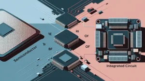
A reliable BGA manufacturing process should not rely on surface finish selection alone. Engineers and manufacturers should establish controls throughout the complete production workflow.
A typical process includes:
- Review the BGA component datasheet.
- Confirm the recommended PCB footprint.
- Check BGA pitch and pad dimensions.
- Select an appropriate PCB surface finish.
- Perform DFM and DFA review.
- Verify solder paste specifications.
- Optimize stencil aperture design.
- Verify solder paste deposition using SPI.
- Confirm component placement accuracy.
- Optimize the reflow temperature profile.
- Inspect solder joints using AOI and X-ray where appropriate.
- Perform electrical and functional testing when required.
A complete PCBA manufacturing workflow can integrate PCB fabrication, component sourcing, SMT assembly, inspection, testing, and final assembly to reduce communication gaps between separate suppliers.
Conclusion
BGA packages provide significant advantages in high-density electronic design, but their hidden solder joints also make manufacturing quality more demanding.
The BGA PCB surface finish is one of the factors that should be carefully evaluated because uneven solder thickness can contribute to poor coplanarity, weak solder joints, open connections, and solder bridging.
For fine-pitch applications, an ENIG PCB or suitable OSP PCB can provide a flatter and more consistent pad surface than conventional HASL in many applications.
Ultimately, reliable BGA assembly depends on the combination of PCB design, surface finish, solder paste printing, component placement, reflow control, inspection, and testing.
When the BGA pitch is small and product reliability is critical, engineers should prioritize surface consistency and process control rather than selecting a PCB finish based solely on initial cost.