BGA Fanout and Escape Routing
The Escape Problem
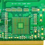
A ball grid array presents its connections on a grid of pads, and only the outermost row is directly accessible. Every other ball has to reach the rest of the board through a via, and those vias have to be placed without touching one another and without blocking the paths of the balls behind them. Fanout, or escape routing, is the arrangement that solves this. It is decided almost entirely by the ball pitch, the pad diameter and the via size, and it usually determines how many layers the board needs before a single signal has been routed to its destination.
Row by Row
The classic approach escapes the outer rows first and works inwards. The first row of balls goes to vias placed just outside the package footprint, where there is open space. The second row routes out between the pads of the first row and places its vias further out. Each subsequent row needs a channel between the vias of the row in front of it, and the channels run out quickly. With a typical pad and via combination, the fourth row is often the last that can be escaped on the top layer, and everything deeper has to go to an inner layer or use a different via strategy. The counting is straightforward but unforgiving: one via too wide and the channel behind it disappears.
Via Patterns
The conventional pattern is the dogbone, where a short trace runs from the pad to a via placed beside it. It is cheap, it needs only a standard through via and it uses the top layer for the connection. The alternative is via in pad, where the via sits inside the pad itself, which removes the stub trace and frees the space beside the pad for the channel behind it. Via in pad is more expensive and requires filling and capping, but it is what makes the deeper rows reachable on dense packages. A third pattern places vias on a grid offset from the balls, with traces running at an angle to reach them, which can be more efficient in some geometries but is harder to inspect.
Dogbone, Via in Pad and Microvia
The choice between them follows from the pitch. At 0.8 mm or wider, dogbones are comfortable and the escape usually closes in a few layers. At 0.5 mm the space beside the pad is small, and the dogbone becomes marginal. At 0.4 mm and below, via in pad or a microvia-in-pad arrangement becomes the practical answer, because there is no room for a via beside the pad. Where the pitch is fine and the package is large, a build-up layer with laser microvias is often what allows the inner rows to escape at all, since the smaller via frees a channel that a mechanical through via would fill.

Layer Count and Channels
The number of layers is set by the escape, not by the total net count. If a package has twenty rows and the fanout can only release four rows per layer, at least five signal layers are needed to reach them all. The way to reduce that number is to free channels: use a smaller via, use via in pad, increase the spacing between the ball pads (difficult, since it is fixed by the package), or route the escape on both sides of the package so that signals leave in two directions. The last option is often overlooked and can halve the density on one side of a large device.
Plane Integrity Under the Package
The vias from a BGA punch through the reference planes beneath it, and the antipads they require remove copper from those planes. On a fine-pitch device the antipads can consume so much of the plane that what remains is a mesh of narrow necks, which is both a return path problem and a fabrication problem. The design should check the plane under the package for continuity, use the smallest antipad the process allows, and consider routing the escape so that the vias are distributed rather than clustered. Where the plane is unavoidably fragmented, a second ground layer stitched with vias is usually the answer.
Design Checks
Check the escape before routing anything else, because it sets the layer count. Verify the via-to-via and via-to-pad clearances against the process, and confirm that the dogbone stub is short enough for the frequencies involved. Check that the plane beneath the package remains continuous for the return paths of the fastest signals. Confirm the via-in-pad locations are on the drawing and that the assembly drawing shows them. Finally, check that the escape does not place a via so close to the package outline that the assembly fixture or the stencil cannot be positioned.
Fanout and Assembly
The escape pattern also decides what the assembly process sees. A dense field of via-in-pad sites means the stencil has to print onto filled and capped pads, which changes the aperture design and reduces the paste volume each pad can accept. An escape that places vias very close to the package outline can leave the stencil with no room for its own border, and a stencil that cannot be positioned correctly ruins the whole assembly rather than one joint. Where a package has a large thermal pad surrounded by a fine-pitch perimeter, the paste printing, the placement and the reflow all have to be settled before the fanout is frozen, because changing the via pattern afterwards means changing the stencil and the whole process that was qualified with it. Involving the assembly house at the fanout stage is far cheaper than re-qualifying the process later.

FAQ
How many rows can escape on one layer? Usually three to four with dogbone vias at a normal pitch, fewer as the pitch gets finer and more with via in pad or microvias.
What is a dogbone via? A via placed beside a BGA pad and connected to it by a short trace, forming the shape that gives it its name.
When should I use via in pad? When there is no room beside the pad for a via, which happens at fine pitch or on deep rows where the channels are consumed.
Does the fanout determine the layer count? Usually yes. The escape is the densest region of the board and it decides how many signal layers are required.
Why does the plane under a BGA matter? Because the antipads remove copper from the reference planes, which can fragment the return path and complicate fabrication.
Conclusion
The fanout is the first thing to solve on a BGA layout, because it fixes the layer count and the via strategy for the whole board. Count the escaping rows for the chosen via, free channels with the smallest via the process allows and via in pad where the pitch demands it, and check the plane under the package for continuity. Package and via capability is described under PCB capabilities, the drilling and filling steps are covered in PCB manufacturing, and the channel and plane rules belong to PCB design and layout. Dense packages are normally proven through prototype PCB assembly in 2026.