Board Support and Backing Systems for Reliable SMT Assembly
A printed circuit board is flat when it is manufactured and flexible when it is being processed. In a printer, a placement machine or a reflow oven the board is pushed, pressed and heated, and it will bend unless something holds it flat. Board support is the unglamorous hardware that prevents that bending, and many of the faults attributed to paste, placement or profile on a thin board can be traced back to it. The hardware itself is simple; the discipline of setting it correctly for every product is not.
Why Support Matters in Printing and Placement
In the printer the squeegee presses down on the stencil with a force measured in kilograms, and the board underneath has to resist it. If the board flexes away from the stencil the gap between them changes, the paste volume changes with it, and the deposit becomes uneven across the panel.
In placement every nozzle that touches the board applies a small force, and a board resting on a few pins will deflect under the sum of them. The deflection appears as a placement offset that varies with position across the panel, which is easy to misdiagnose as a vision or calibration problem.
The Forces Acting on the Board
Three forces matter: the compression of the squeegee in printing, the placement force of the nozzle, and the thermal movement in the oven. The first two are mechanical and can be measured, while the third is a consequence of heat and cannot be removed, only managed with support and a suitable profile. The board behaves like a beam, so deflection falls with the cube of its thickness and rises with the cube of the span between supports, which is why pin spacing matters more than pin quantity.
Their magnitude depends on the process. A high speed printer with a wide squeegee applies more force than a slow one, and a machine placing large connectors applies more than one working with chip components, so the support system has to be sized for the worst case on the line.
<img src="https://www.gopcba.com/wp-content/uploads/2025/08/14.png" alt="Support pins arranged under a PCB in a printing machine” />
Support Pins, Blocks and Vacuum Plates
Magnetic or pneumatic pins are the usual solution, placed in a grid under the board so that populated areas are supported without touching the components. The pins are set to a height that matches the underside of the board, and their positions have to be recorded for each product.
A vacuum plate holds the board against a flat surface across its whole area and is the most effective method for a thin panel. Blocks and profiled supports are used where a board carries tall parts on the underside and needs clearance in specific places. A rigid backing plate is the simplest form of support for a short run, since it holds a large area flat without any layout being programmed.
Support in the Printer
The printer has the most demanding requirement, because the force is applied over a small area and any flexure changes the paste volume directly. Support here is normally a combination of a vacuum table, pins around the panel edge and a tooling block that follows the board outline.
The stencil and the board must also be able to separate cleanly after printing. A board that is held too firmly, or that is not level, will not release the stencil evenly, and paste will be pulled back out of the apertures on one side of the panel. Clamping around the panel edge should be firm enough to hold the board without distorting the corners, and the clamps should be checked for wear at the same time as the pins.
Support in Placement and Reflow
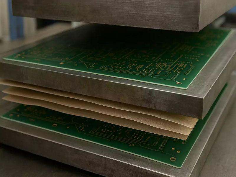
In placement the requirement is flatness rather than rigidity. A board that is flat when the first component is placed has to remain flat enough for the last one, and a warped board changes the effective placement height across the panel.
In the oven the board is supported by the conveyor rails alone and it will sag under its own weight as the laminate softens. A centre support rail or a mesh belt for a thin board is often the only way to keep the assembly flat through the peak.
Double Sided Boards and Rework
A board that already carries components on the underside cannot be supported by pins in those positions, so the support has to be designed around the existing parts. Custom profiled supports or a dedicated tooling plate are common for a high volume product. The support positions themselves are usually held in the machine program, so a change of product means a change of layout rather than a rebuild of the tooling.
Rework adds a further complication, because local heat and the pressure of a hot air nozzle can deflect a small area of the board. A support placed directly under the site, or a vacuum fixture, keeps the pad in plane during the operation.
Effects of Poor Support: Warp, Coplanarity and Cracks
Poor support produces a characteristic set of faults. Paste deposits vary across the panel, fine pitch parts show placement offsets that follow the board position, and solder joints on a warped area open at the edge of the package. Warpage also changes the height of the board relative to the stencil and the nozzle, so the faults tend to appear in the same region of every board.
On a ceramic component the deflection can be enough to crack the body, and the crack may not appear until thermal cycling later in the product life. That physical damage is the most expensive consequence of a support problem, because no adjustment to the process will undo it, and the pattern is described in the guide to solder defects and board failures.
Setting Up and Verifying Support
Setup begins with the board outline and the underside layout, from which the pin positions are chosen. The support should be checked by looking for gaps between the board and the pins with the board clamped in the machine, rather than by eye from above.
Verification uses the paste deposit measurement, the placement offset data and, where the board is thin, a flatness check before and after the process. Comparing a supported run with an unsupported one on the same product is the quickest way to see whether the support is adequate. The check should be repeated after any change of tooling or of board supplier, because a small change in laminate stiffness is enough to alter the deflection.
Choosing a Support Strategy for a Product
The choice depends on the thickness and size of the board, the mass of the components, the underside layout and the production volume. A thin board with a high component count justifies a dedicated vacuum tooling plate, while a small rigid board may need only a few pins.
The strategy should be documented with the product, alongside the board outline and its tolerances, because the pin layout is part of the setup and a change of operator should not change the support. Records of the layout, the tooling used and the verification result are what make the process repeatable.
FAQ
How many support pins are needed? Enough that the board cannot flex between them under the process force, which is set by the board thickness and the stiffness of the laminate. The spacing is normally found by testing rather than by calculation.
Can support pins damage the board? They can mark the solder mask if they are dirty or if the height is wrong, and they can press on a component if the layout has not been checked. Pin tips should be clean and the layout verified against the assembly drawing.
Does support matter for a thick board? Less than for a thin one, but it still matters for fine pitch printing, because the force of the squeegee is concentrated and even a small deflection changes the deposit.