Castellated Hole FR4 PCB: What Designers Need to Know
A castellated hole is a plated through hole that is drilled on the edge of a panel and then cut in half during routing, leaving a plated semicircular notch along the board outline. The result looks minor but changes everything about how a small module attaches to a larger board: the castellations can be soldered directly onto matching pads like a surface mount component, so no connector is needed at all. For designers building radio modules, sensor packages or power bricks that must drop onto a carrier board, understanding how a castellated hole FR4 PCB is specified, fabricated and inspected removes most of the risk from the approach.
How Castellated Holes Work
Fabrication starts with a normal plated through hole positioned so that its centre lies exactly on the final board outline. Copper is plated through the barrel as usual, the outer layers are patterned, and the surface finish is applied across the whole hole. Only at the very end, during profile routing, does the cutter pass along the outline and remove half of each hole, exposing the plated inner wall as a concave pad. The remaining copper must be thick enough to survive that cut without smearing, which is why castellation is normally specified with a minimum copper thickness rather than the standard plating class of the rest of the board.
The distinction from a conventional plated through hole is functional rather than structural. A through hole exists to accept a component lead or to connect layers, and it sits inside the board where nothing can reach it. A via performs the same layer-to-layer connection but is expected to be covered or tented and carries no mechanical load. A castellation is expected to be soldered to a pad on another board and to carry both current and mechanical load, and it is inspected on the cut face rather than from above.
Why FR4 Remains the Default Substrate
FR4 is a woven glass fabric bonded with an epoxy resin, formulated to be flame retardant, and it is produced in enormous volume for general purpose circuit boards. That volume is the reason it is cheap, widely available in every thickness and copper weight, and compatible with every standard fabrication and assembly process. For a castellation module the mechanical properties matter as much as the electrical ones: the laminate must hold the plated barrel firmly enough that routing and subsequent handling do not crack the copper away from the resin.
Higher performance materials do exist. Polyimide laminates tolerate continuous temperatures that FR4 cannot, and they bend where FR4 would break, which makes them the choice for flex and rigid flex products. Ceramic-filled and PTFE-based materials offer much lower loss at microwave frequencies. Both cost several times more than FR4 and are far harder to source in small quantities. A module that operates below a few gigahertz, stays within the thermal limits of the laminate and does not have to flex has no reason to pay that premium, and the table below summarises the usual trade-off.
Comparing Substrate Options
FR4 sits at the low-cost end with good electrical performance and moderate thermal conductivity. Polyimide costs more and offers noticeably better thermal performance and far better behaviour at temperature extremes. Metal core substrates are a middle-cost option with excellent heat spreading, but they are limited to simple constructions and are not usually offered with castellations.
The practical rule is to select on the basis of the worst-case condition the module will meet. If the answer is an ambient of sixty degrees and a few watts of dissipation, FR4 with a generous copper weight and thermal vias to the inner planes will be entirely adequate, and a metal core or ceramic substrate would add cost and lead time for no benefit.
The Manufacturing Sequence
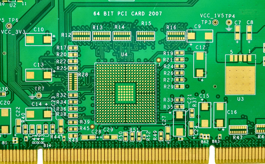
Drilling comes first, using controlled-depth or high accuracy mechanical drilling to place each castellation hole precisely on the outline. Plating follows, and this is the step that decides whether the module will be reliable, because the copper must be uniform around the full circumference of the barrel and must be well bonded to the resin. Patterning and etching define the traces, the pads and the connection to each castellation, and the surface finish is then applied to protect the copper that will later be exposed by the cut.

Profiling is performed last, and it is the step that distinguishes a routine order from a demanding one. The router has to follow the outline without chipping the laminate, without tearing the copper away from the barrel edges and without leaving burrs that would prevent the module from sitting flat on its carrier. A second routing pass at a different depth, or a controlled-depth score before routing, is often used so the cut face stays clean. Final inspection covers the appearance of the cut face, plating adhesion and electrical continuity through every castellation.
Design Rules That Keep Yield High
Hole diameter typically falls between 0.3 mm and 0.6 mm, with the smaller end reserved for fine-pitch modules where pad space on the carrier board is limited. The pitch is set by the placement capability of the assembly line and by the requirement that the carrier pad be at least as wide as the castellation plus a small tolerance. Plating thickness should be specified explicitly rather than left to the default, since the cut face is a solderable surface and thin plating will wick solder away from the joint.
The outline must be defined so that the castellation centre sits exactly on it; a hole placed a few hundredths of a millimetre off centre produces an asymmetric notch that is difficult to inspect and inconsistent from board to board. Keep the copper connecting each castellation to the internal circuitry short and wide, avoid placing vias directly behind the castellation where the drill could break into the barrel, and leave solder mask clear of the notch on both the module and the carrier. Our design release checklist lists these items in the order they should be verified.
Applications and Assembly Notes
Module-to-board connection is the dominant use. Radio modules, power converters, memory packages and sensor assemblies are all commonly produced as castellated sub-boards that are soldered onto a carrier, which allows the module to be tested on its own before it is committed to the finished product. Consumer devices use the same idea to save the height and the cost of a connector, and industrial and automotive designs use it where vibration makes a pluggable connection a liability.
Assembly requires a stencil aperture that deposits enough paste to form a fillet on the cut face without pushing the module off its pads, and the placement machine needs a vision system that can recognise the castellation pattern. Thermal profiles are similar to any other surface mount assembly, but the module usually has more thermal mass than a comparable component, so the soak time may need extending. Our stencil fabrication notes describe how the aperture is derived from the pad geometry.
Inspection and Common Defects
The defects that matter are visible on the cut face. Incomplete plating leaves a bare or thinly covered area that will not wet properly, and it is caused by poor throwing power in the plating bath or by plating that was specified too thin. Rough or torn edges indicate a worn router bit, an aggressive feed rate or insufficient support during profiling, and they reduce the contact area of the finished joint. Contamination on the notch, often from an incomplete resist strip before finishing, produces a joint that looks sound but fails in thermal cycling.
Visual inspection under magnification catches most of these before assembly, and a cross section on a sample from each panel confirms plating thickness and the integrity of the copper-to-resin bond. Electrical continuity across every castellation is a fast additional check. Our component tolerance and reliability notes explain how the resulting joint is assessed for thermal cycling stress.
FAQ
What is the difference between a castellated hole and a normal plated hole? The hole itself is plated in the same way, but a castellated hole is positioned on the board outline so that routing cuts it in half. What remains is an exposed plated semicircle that can be soldered to a pad on another board.
Can any FR4 thickness be castellated? Thinner laminates are easier to cut cleanly and are used for most small modules, but standard thicknesses can be castellated with the right routing parameters. The plating thickness and the routing process matter more than the laminate thickness itself.
How many times can a castellated module be reflowed? The module can normally survive the same number of reflow cycles as any other surface mount component, provided the plating is thick enough and the cut face is clean. Repeated rework at the joint is far more damaging than the original assembly cycle.