Castellated Holes: Design Rules and Process Limits
Castellated holes are plated holes cut in half along the edge of a board so that the remaining semicircle can be soldered to a parent board, a technique used by almost every radio module, sensor module and power module on the market. The idea is simple and the process is not: cutting a plated barrel open without tearing the copper is one of the more demanding operations in board fabrication.
What Castellated Holes Are
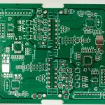
A castellated hole is a plated through hole positioned on the board outline and then cut through during profiling, leaving a plated semicircular recess. The module is placed on a parent board and reflowed, and the solder fillet forms on the exposed half barrel.
That construction solves a real problem. A module attached with round holes or with edge connectors is bulky, and the alternative of soldering wires is slow and unreliable. The half hole gives a low profile connection with a visible joint, as described in general practice for board outline features.
<img src="https://www.gopcba.com/wp-content/uploads/2026/08/Box-Build-Components.webp" alt="Castellated holes along the edge of a PCB module board” />
Why the Process Is Difficult
Profiling removes part of the barrel. If the copper is soft and unsupported, the cutting tool drags it, which leaves burrs, tears or lifts the plating away from the wall. The result is a hole that looks acceptable in a photograph and fails electrical test or field assembly.
Registration is the second difficulty. Drilling position, material movement during lamination and profiling accuracy all accumulate, so the two halves of the same hole can end up different sizes. On a module edge with a row of holes, that variation is visible and it interferes with soldering.
The Conventional Flow and Its Weakness
The traditional sequence drills and plates the holes, patterns the outer layers, applies mask and finish, and then cuts the outline. The half hole is created at the end, when the barrel is fully formed and protected only by the plating itself.
In that sequence the cutting operation is the last mechanical step before the board is finished, so any damage is permanent. Copper slivers, lifted plating and torn walls all originate at this point, and they are the reason castellated modules have a reputation for being harder to build than their geometry suggests.
Why Copper Support and Barrel Damage Matter
The plating on the hole wall is thin compared with the surface copper, and it is anchored at both ends where it meets the outer layers. When the tool passes through, the copper is supported by the connection to those layers and by whatever covers the wall.
A protective layer over the barrel during cutting therefore changes the outcome. Where the wall is covered, the tool cannot drag the plating directly, and where the covering is metallic it also carries the mechanical load. That is the principle behind the improved sequences used by experienced fabricators.
An Improved Manufacturing Sequence
A more robust approach plates the hole and then adds a tin layer over the copper before the outline is cut. The tin covers the barrel and is fully connected to the outer copper, so when the cutting tool passes, the load is carried by a continuous metallic layer rather than by a thin plated film.
The half hole is formed, and only then is the film stripped and the surface etched. Because the etch follows the cut, the copper surface is not left exposed and oxidised between the two operations, which removes the main source of residual copper and the shorts it causes.
Design Rules for Castellated Edges
Hole diameter, pitch and the distance from the hole to the adjacent features are set by the fabrication limits rather than by preference. A typical module edge uses holes around 0.6 mm on a pitch near 0.45 mm, with the outer layer patterning kept clear of the cut line.
Annular ring matters as much as the hole. Where the pad is only slightly larger than the hole, a teardrop or a widened connection is often added so that the plating has support after half of it has been removed, and the trace leaving the pad should approach from a direction that survives the cut.
Panel Design and Breakaway
A module board is usually supplied in a panel, and the way they are separated affects the half hole directly. Panel routing with a clean path through the holes is preferable to a v-score, which cannot cut through plating without deforming it.
Tabs and rails have to allow the router to approach each hole along the outline. A tab placed in the middle of a row of half holes forces the tool to stop and restart, and it is at those points that the copper is most likely to be damaged.
Inspection and Acceptance
Inspection looks for burrs, lifted plating, copper particles and the amount of barrel remaining. A half hole that is smaller on one side of the module than the other is a registration problem, not a finishing one, and it will show up as a soldering difference in assembly.
Electrical test verifies that the connection through the half hole is intact, and a sample should be cross sectioned to confirm the plating thickness on the wall. Visual inspection alone cannot tell whether the plating survived the cut.
Assembly Considerations
The joint is formed on a curved surface, so the solder has to wet the half barrel and the parent board pad at the same time. Paste volume is usually increased at these positions, and the pad on the parent board is extended slightly beyond the module edge to give the fillet somewhere to form.
Mechanical support is often required as well, because the connection is not intended to carry the whole load of a module. Adhesive or a small bracket is normal practice, particularly where the module carries a connector that will be plugged and unplugged.
Half Holes Versus Edge Plating
Both techniques connect a module at its edge, and they are not interchangeable. A half hole gives a solderable joint that can be inspected visually and reworked with an iron, while edge plating provides a continuous conductive surface along the side of the board with no hole at all.
Edge plating suits antenna feeds and shielding connections, where the requirement is a low impedance path rather than a mechanical joint. Half holes suit modules that must be soldered down, and the choice should follow the assembly method rather than the appearance of the finished part.
Tooling and Fabrication Notes
The fabrication drawing should identify the half holes explicitly, state the finished size and the tolerance, and confirm whether the plating must extend to the cut face. The drill chart should distinguish them from ordinary through holes, since they are handled differently at profiling.
Registration tolerances belong on the drawing as well. If the two halves of a hole on opposite edges must match within a defined limit, saying so allows the fabricator to plan the drilling and profiling accordingly rather than discovering the requirement at inspection.
Cost and Lead Time
Castellated modules cost more than an equivalent plain board because of the additional care at profiling and the higher inspection rate. The premium is modest when the panel is designed sensibly and larger when the layout forces a difficult cut or a tight tolerance.
Lead time is affected mainly by the review that precedes the build. A fabricator that has to work out the sequence from an unfamiliar design will allow extra time, and one that receives a drawing which states the requirements clearly can schedule the work normally.
FAQ
Can any board house produce castellated holes? Many can, but quality varies. The process requires a specific sequence and careful profiling, so the capability should be confirmed with a sample rather than assumed from a general quotation.
What causes copper burrs on the half hole? Cutting a plated barrel without protecting it. Burrs appear when the tool drags the plating, which is why the tin protected sequence produces a cleaner edge.
Do castellations need a special surface finish? They need a finish that survives the cut and remains solderable, so a flat, metallic finish is normally used rather than one that can be mechanically damaged.