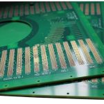
Castellated PCB: Half Holes for Module Assembly
Castellated holes are half holes cut through the edge of a board so that the module can be soldered flat onto a carrier like any other surface mount component. They are the reason a small power module or a radio module can be assembled without a connector, and in a castellated PCB the board outline itself becomes a critical tolerance rather than a mechanical detail.
What a Castellated Hole Is
A castellated hole, also called a half hole or a plated edge castellation, is a plated through hole that is drilled on the board outline and then cut in half during routing. What remains is a semicircular plated pad on the edge of the board, open on the outside and connected to the internal layers through the remaining half of the barrel.
The result behaves like a very short surface mount pad with a much larger cross section. Solder wets the inside of the semicircle and forms a solder fillet that is visible from the side, which makes inspection straightforward even though the joint is on a vertical face rather than a horizontal pad.
Why the Design Uses Them
The primary reason is height and footprint. A connector occupies vertical space and adds its own footprint and its own cost, while a castellation uses the edge of the board that was going to be there anyway. On a module that is only a few millimetres tall, that difference decides whether the product fits.
The second reason is electrical. A castellated connection has a short path to the internal layers and very little inductance compared with a connector, which matters for a power module carrying fast switching currents or a radio module carrying a high frequency signal. The third is manufacturability: module assembly can be completed by the same machine that places the other components, with no separate process step or manual operation.
Design Rules for the Board Edge
The castellation diameter and the pitch are the two numbers that define the interface. A common diameter is around 0.6 to 1.0 millimetres with a pitch of 1.0 to 2.0 millimetres, and the pad on the outside should be about 0.2 millimetres wider than the drill on each side so that a fillet can form.
The hole must be placed so that the centre line lies on the board outline, which means the outline tolerance directly affects the finished feature. The fabricator needs an explicit note on the drawing, because a hole that is simply placed close to the edge will not produce a usable castellation. The copper on both sides should be tied together around the hole with an adequate annular ring, following the same rules as any plated barrel.

How the Board Is Cut
Castellations are formed after plating, during the routing operation that separates the boards from the panel. The router follows the outline and cuts through the plated holes, which is why the hole pattern has to be defined in the fabrication data rather than left to the fabricator to infer.
Two details decide whether the result is clean. The first is the routing order relative to plating: the holes must be plated before the cut, or the barrel will be open. The second is the router bit diameter, which limits how sharp the resulting geometry can be and how much burr is left on the cut edge. A deburring step is normally required, and the cut surface should be inspected for smearing of the copper.
Soldering and Assembly
The module is placed on the carrier and reflowed with the rest of the assembly. Paste is deposited on the carrier pads, which should extend slightly beyond the module edge so that a fillet can form on both the top face and the vertical face of the castellation.
Because the joint is on a vertical surface, the amount of solder that forms the fillet depends on the paste volume and on the wetting of the castellation barrel. A barrel that has been smeared by the router will not wet, which is the most common cause of a weak joint on a castellated module. The assembly considerations resemble those for any fine pitch part, described in placement order and pad positioning, and the mechanical constraints of the carrier are covered in board outline and mounting design.
Mechanical Strength and Reliability
Castellated joints are strong in shear but relatively weak against peel, because the bond line is short. A module that will be subject to bending or to cable pull should have additional mechanical fixing, such as a screw, a clip or a fillet of adhesive along the edge.
Thermal cycling is the second concern. The castellation, the carrier pad and the solder form a joint with three different expansion coefficients, and repeated cycling will eventually crack the barrel if the module and the carrier expand differently. Keeping the module small and the joint symmetric reduces the stress, and the same principle applies to any solder joint on a mixed material assembly, as it does to the barrel construction described in via in pad or plated through.
Inspection and Rework
Inspection of a castellated joint is visual from the side, which is an advantage over a hidden joint but still requires access. The board should be placed on the carrier so that the module edges face outward, and the assembly drawing should call out which sides must remain visible after reflow.
Rework is more difficult than on a flat joint, because a soldering iron cannot easily contact both the castellation and the carrier pad at once. Hot air is usually the method of choice, with the module held in place while the joints reflow. Where a module has many castellations, a preheater is normally required to bring the whole assembly up to temperature evenly.
Cost and Yield Considerations
The extra cost of a castellated design comes from the additional process control rather than from material. The outline must be held to a tighter tolerance, the routing has to be programmed around the hole pattern and the cut edges may need a deburring step. On a small module the cost per unit is modest, but it is real and it should be included in the comparison against a connector.
Yield is affected by the same tolerances. A castellation that is cut slightly off centre leaves a smaller plated area, which reduces the joint strength without producing an obvious defect. That is why the outline tolerance and the drill position are usually called out as controlled dimensions on the drawing rather than left to the general tolerance block.
FAQ
Can castellated holes be added to an existing design? They can, but the outline and the hole placement both change, so the board needs a new revision. The castellation must be centred on the outline, which is a change to the mechanical drawing as well as the artwork.
What is the minimum pitch for castellations? Around one millimetre is a practical limit for reliable assembly, since the routing step has to cut cleanly between adjacent holes. Tighter pitches are possible but reduce the yield and the joint strength.
Are castellated modules harder to test? Slightly, because the connections are on the edge rather than on a surface that a probe can press. Test points are usually added on the module itself so that it can be verified before it is assembled onto the carrier.