Chip Resistor Precautions: Six Handling Rules for PCB Assembly
Chip resistors are among the most widely used components in printed circuit board assembly, and among the easiest to take for granted. A surface mount resistor is a small ceramic body with two terminations and a thin resistive film, and on dense boards the whole part may be smaller than a grain of rice. When hundreds of them are placed into every design, one wrong value, one damaged film, or one overheated termination can leave a board that looks perfectly assembled yet performs incorrectly in service. That is why experienced PCBA manufacturers treat the detection, selection, and handling of chip resistors as one of the most important links in assembly.
This article sets out six chip resistor precautions that belong before and during production: safe measurement, value verification, potentiometer maintenance, rated power margin, tolerance selection, and soldering heat control. Each rule is simple on its own, yet together they prevent the rework, intermittent faults, and field returns that quietly raise the real cost of every board.
Why Chip Resistor Handling Needs Its Own Checklist
Chip resistors appear in nearly every functional block of a modern board, from current limiting and voltage division to pull-up networks, timing, filtering, and feedback paths. Their tiny packages enable dense designs but make identification difficult: the value marking on the smallest bodies is unreadable without magnification, and similar looking reels are easily confused on the line. An out of specification resistor does not always fail immediately; it may run hot, drift with temperature, or bias a circuit slightly out of range, and the symptom is usually blamed on another component first. Such errors are expensive to find later, because functional testing proves that a board works, not that it works at the intended design point.
The precautions described below are applied by gopcb engineers before every SMT PCB assembly run, and they focus on the moments where resistor faults actually begin: measurement, placement, and soldering. The routine costs little and removes the most common sources of value errors and heat damage before a board reaches test.
Measure Chip Resistors with the Power Off and the Part Isolated
The first precaution applies whenever a multimeter is used on a chip resistor inside an assembled circuit: disconnect the power supply before anything else. Measuring a live circuit is unsafe for the operator and meaningless for the result, because the voltage present can disturb the meter and the reading includes current paths unrelated to the part under test. Power the board down, let the capacitors discharge, and only then begin.
The second precaution is to isolate the component. Disconnect at least one end of the chip resistor from the rest of the circuit before measuring, because a resistor left in place sits in parallel with other parts and the meter shows the combined network resistance instead of the single resistor value. Do not grip both probes with your hands at the same time: the human body forms a parallel resistance path that can pull a high value reading out of range, so use clip leads or a small fixture whenever possible. Set the meter range before touching the probes, and read only after the display stabilizes. When high precision is required, for example to verify a tight tolerance part, use a resistance bridge or a four wire setup, both of which remove lead and contact resistance from the result.
Verify the Value and Marking Before Placement
Before placement, the value of a chip resistor should be confirmed from its marking and from a measurement. Surface mount resistors carry printed codes, three or four digits for standard parts and a two digit letter code for precision series, and a magnifier is usually needed to read them on small bodies. Compare the code and the measured value with the bill of materials, and confirm that the reading falls inside the stated tolerance band. The check takes seconds per sample and catches mixed reels, wrong tapes, and mislabeled components before they reach the board; rejecting them here is far cheaper than desoldering them after reflow.
Parts that pass the check should be placed with the marking side facing upward, because the printed side gives operators, automated optical inspection, and rework technicians a reliable way to identify the component later in the process. Resistors without readable markings should be verified by measurement and tracked by reel so that their origin stays traceable. Incoming verification of this kind works together with component procurement, because a supplier lot that arrives unchecked can hide value spread across several reels.
Potentiometer Care: Noise, Cleaning, and Replacement
Potentiometers, the adjustable resistors used for calibration and trimming, fail differently from fixed chip resistors. After long service they tend to develop high noise and intermittent contact faults, and open frame types without a protective housing are affected more often than sealed versions. The usual root cause is the resistive film: the wiper wears the track during adjustment, dirt and carbon powder accumulate on it, and the contact resistance becomes unstable. The symptoms are crackling when the setting moves, jumps in resistance, or an open circuit at exactly the position where a stable value is needed.
When the condition is light, the film can be cleaned with isopropyl alcohol to remove the dirt and carbon powder left by friction; let the part dry completely and avoid bending the wiper while cleaning. When the damage is serious, cleaning cannot restore a worn film, and the potentiometer should be replaced with a new part. Before assembly, rotate the wiper through its full range while watching the resistance reading and listening for noise, and in dusty or humid products choose a sealed trimmer so the adjustment remains stable for the life of the board.
Select the Rated Power with Enough Margin
Rated power is decided at the design stage, and the assembly line can only execute that choice. A chip resistor rated far above its real dissipation increases body size and cost and makes a dense layout harder; a rating that is too low is worse, because the part overheats, its value drifts, its film ages quickly, and the surrounding solder joints are stressed by repeated heating. As a working rule, the rated power should be roughly twice the power actually dissipated in normal operation, so a part that carries 0.1 watts should be specified at 0.2 watts or at the next standard rating above that value.
The factor of two is a starting point, not a guarantee. Inside a hot enclosure, near other heat sources, or under continuous load, apply extra derating, and follow the derating curve published for the specific part rather than assuming the nominal rating always applies. When the circuit drives the resistor with short pulses, check the pulse capability as well, because a brief overload can damage the film even when the average power looks safe. The pads and traces also remove heat from the body, so a resistor running near its limit needs a sensible copper area around its terminations.
Match the Tolerance to What the Circuit Needs
Tolerance describes how far the actual resistance may deviate from the nominal value, and it should match the function the resistor performs. Many general purpose circuits work correctly when chip resistors sit within roughly 5 percent or 10 percent of the values shown in the schematic, because the surrounding components absorb the variation. Timing circuits, feedback dividers, current sensing networks, and voltage references are different: a ten percent part there can push the output outside specification, so the drawing must call out a tighter tolerance such as 1 percent or 0.5 percent. Precision requirements should be marked separately on the schematic and the bill of materials, so that a general purpose part is never substituted during procurement or placement.
Tolerance is not the only source of value spread. The temperature coefficient moves the resistance as the board heats, and aging shifts it slowly over the years, so precision positions should be filled from a single batch and verified by measurement before assembly. When a sample sits at the edge of its allowed band, consider whether the circuit accepts that value at both temperature extremes; if not, select the tighter part while the position is still on the bench.
Solder Small Chip Resistors with Controlled Heat
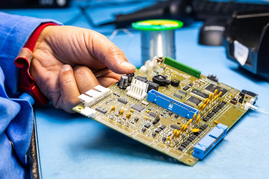
A chip resistor body is small, so it heats and cools quickly, and the resistive film inside is easily damaged by excess temperature. When soldering or reworking such parts by hand, use a fine, sharp tip and keep the iron power low, typically below about 30 watts for a manual iron, or use a temperature controlled station set to a moderate value matched to the solder alloy. Keep the tip in contact only long enough to form a good fillet, because an overheated film can drift permanently out of tolerance even when the component still looks normal.
The same care applies to resistors with leads in mixed technology boards. Do not trim the leads very short before soldering: a short lead conducts heat straight into the component body, so leave enough lead for the heat to spread, make the joint, and trim only after the part cools. Hand soldering remains one of the most common sources of damage in an otherwise sound PCB assembly process, so treat every rework operation with the same controlled-heat rules that apply on the production line.
Build the Six Precautions into the Assembly Routine
Reduced to a routine, the six precautions become a short checklist: measure with the power off and the part isolated; verify value and marking before placement; clean lightly contaminated films and replace worn potentiometers; choose a rated power near twice the actual dissipation; match tolerance to the function and flag precision positions; and solder with controlled heat and untrimmed leads until the joint cools.
A checklist works only when it is enforced consistently. These checks belong in the incoming inspection record, the first article review, and the process instructions for the line, and the results should stay visible to the team that runs PCBA testing, where automated optical inspection and electrical tests catch the value errors and damaged films that visual checks miss. When a field failure points back to a resistor, these records usually show at once whether the part was mis-selected, mis-measured, or mis-soldered.
How gopcb Applies These Rules on Its Assembly Lines
gopcb follows these chip resistor precautions on every order. Incoming components are verified against the bill of materials, small packages are checked under magnification, marking orientation is controlled during placement, and power rating and tolerance choices are reviewed with the customer before production starts. Soldering runs under validated profiles with calibrated irons, and first article inspection confirms the finished board before the full batch is released.
For products that need the whole chain coordinated, gopcb combines board fabrication, component sourcing, and assembly in one turnkey PCB assembly program, so component selections, process records, and test data stay under a single roof. Send gopcb your Gerber files, bill of materials, and expected volumes for a free DFM and manufacturability review, and the engineering team will confirm the component choices and process controls that keep your boards reliable from prototype to full production.