PCB Copper Foil Grain Structure and Etch Behaviour
Copper foil is the starting point of every trace on a printed circuit board, and the way it is made decides how it etches, how it adheres and how it behaves at high frequency. Two foils of the same weight and the same nominal purity can produce very different line widths, sidewall shapes and loss figures, because the difference lies in the grain structure produced during manufacturing. This article explains the two production routes, what the grain structure means for the etcher, and how to specify foil so that the process produces what the design expects.
How Copper Foil Is Made
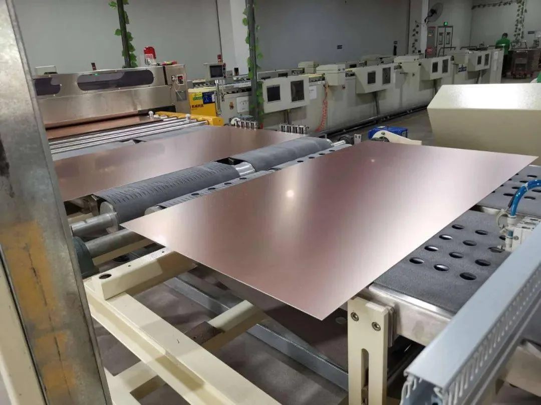
The two commercial routes are electrodeposition and rolling. Electrodeposited foil is grown onto a rotating drum from a copper sulphate solution, and the deposit builds up as a matte, columnar structure. Rolled foil is cast and then reduced by successive rolling passes, which produces a wrought, elongated grain structure and a much smoother surface.
Both routes are followed by a treatment step that roughens one side to promote adhesion and applies a barrier layer to slow oxidation. The treatment is what the laminate bonds to, and it is also what makes the matte side of an electrodeposited foil so rough. The drum side of the same foil is smooth and bright, which is why an electrodeposited foil has two faces with very different properties.
Electrodeposited Versus Rolled Foil
Electrodeposited foil is the workhorse of rigid board fabrication. It is available in a wide range of thicknesses, it is economical and its rough treatment gives excellent adhesion to standard laminates. Its roughness, however, is a penalty at high frequency and a limitation for fine line etching.
Rolled foil is smoother and has better mechanical ductility, which makes it the natural choice for flexible circuits that must survive repeated bending. It costs more, the thickness range is narrower, and its smooth surface needs a different treatment to achieve the same adhesion.

Grain Structure and Directionality
The grain structure of electrodeposited foil is columnar, with grains running through the thickness of the foil. That structure is what produces the nodular matte surface, and it also means that the foil can etch at different rates in different directions if the etchant has a preferred attack.
Rolled foil has grains elongated in the rolling direction, so the material is anisotropic in the plane. Properties such as tensile strength and elongation are different along the rolling direction and across it, which matters for a flex circuit where the bend axis should run across the rolling direction for the best fatigue life.
What Etching Does to the Profile
The etcher removes copper in every direction, not just downwards. The result is a trapezoidal cross section rather than a rectangle: the top of the trace is narrower than the base, and the sidewall is sloped. The slope is a consequence of the chemistry and the process, and it cannot be eliminated, only controlled. The design rule for line width has to account for the fact that the measured width at the top of the trace will be smaller than the artwork figure.
The profile also depends on the foil. A rough foil with a heavy treatment has a large surface area for the etchant to attack, so the effective shape at the base is less defined, while a smooth foil produces a cleaner sidewall. Our etching notes describe how the process is controlled to hold line width.
Etch Factor and Undercut
The etch factor is the ratio of the etch depth to the lateral undercut, and it is the number that describes how well the process holds a vertical wall. A high etch factor means the etchant removed copper almost entirely in the direction of the spray, while a low factor means it removed a large amount sideways.
Undercut is the lateral removal at the base of the trace. It reduces the width of the copper that actually adheres to the laminate and leaves the resist overhanging, which can then fall over and produce a ragged edge. Undercut is worse on a thick foil, because the etchant has to travel further down before the trace is isolated, so the time it spends attacking sideways is longer. Undercut is also worse where the copper density is high, because the local etchant is depleted and the spray has to be run longer to clear the fine spaces.
Fine Line Capability
Fine line capability is limited by the foil thickness as much as by the imaging. A thick foil needs a long etch, and a long etch produces more undercut and a more sloped wall, so the achievable line width and the achievable space between lines both suffer. This is why fine line designs are usually built on thin foil. It is also why a design moved from a two ounce to a one ounce copper weight gains process margin at the same line width.
The relationship is why a design that needs narrow traces and tight spaces should specify the foil weight accordingly rather than asking the etcher to compensate. Our copper balance notes explain how the distribution of copper across the panel affects the etching uniformity.
Adhesion and the Treatment Side
Adhesion comes from the mechanical keying of the treatment into the resin and from the chemistry of the treated surface. The treatment side of the foil is the side that faces the laminate, and it is the side that determines how well the trace survives thermal cycling and mechanical stress. A treatment that is optimised for peel strength at room temperature may not be the one that holds through repeated reflow.
A foil that is too smooth for its laminate may pass the initial peel test and still delaminate after a few reflow cycles, because the thermal expansion mismatch loads the interface. Our laminate properties guide covers how the resin system and the foil treatment interact.
Foil Choice for High Frequency and for Flex
High frequency designs favour a smooth foil, because the current travels in the surface layer and a rough profile lengthens the electrical path. The low profile and very low profile treatments exist for exactly this reason, and our high frequency laminate guide covers how the foil and the dielectric are chosen together.
Flexible designs favour rolled foil, because its grain structure tolerates bending far better than a columnar deposit. Where a rigid flex board has both requirements, the foil may differ between the rigid and the flexible sections, and that difference has to be stated in the fabrication data.
Specifying Foil on the Fabrication Drawing
The fabrication drawing should state the foil weight, the foil type and, where it matters, the treatment class. Stating only the finished copper weight leaves the fabricator free to choose the foil, which is usually acceptable for a general board and not acceptable for a loss controlled or a flexible design.
At gopcb the foil and treatment are recorded with the stack up for each design, and our quality documentation records how the finished trace profile is judged, so that the same combination can be built on a repeat order.
FAQ
Does a thinner foil always etch better? It gives a higher etch factor and less undercut for the same chemistry, which is why fine line work uses thin foil. The trade is a lower current carrying capacity and a higher resistance.
Is rolled foil better than electrodeposited foil? It is smoother and more ductile, which suits high frequency and flexible applications. It costs more and has a narrower availability, so the choice depends on the requirement rather than on quality alone.
Can the etch factor be measured on a production board? It can, by sectioning a trace and measuring the sidewall angle and the undercut. That measurement is the most direct check that the etching process is holding the line width the design expects.