



Decoupling Capacitor Layout and Routing Principles: Hierarchy PCB Design from Low-Frequency Bulk to High-Frequency Ceramic Capacitors
Decoupling capacitor layout and routing is not simply placing capacitors close to power pins. It is a systematic PCB design task that must strictly follow physical and electrical hierarchy relationships. Its core goal is to maintain the impedance at the IC power pins below the target impedance, such as 50 milliohms, across a wide frequency band, usually covering 10 kHz to above 1 GHz. This suppresses power rail noise and prevents synchronous switching noise, or SSN, from causing logic misjudgment or timing violations. The transient current di/dt of modern high-speed digital ICs, such as FPGAs and multi-core SoCs, can reach tens of A per nanosecond. If the decoupling network cannot provide sufficiently fast charge response, it will cause significant voltage droop, where delta V equals L times di/dt, and then induce functional abnormalities.
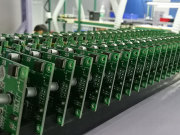
Bulk Capacitor: Low-Frequency Energy Reserve and Ripple Suppression
Bulk capacitors, usually electrolytic capacitors or high-capacitance solid polymer capacitors, with capacitance ranging from 10 to 470 microfarads, undertake system-level low-frequency energy buffering tasks. They mainly deal with power module output ripple from 100 Hz to 1 MHz and long-period load changes. Their key parameters are equivalent series resistance, or ESR, and equivalent series inductance, or ESL. An ideal bulk capacitor is capacitive below 100 kHz, but limited by package leads and internal structure, its actual self-resonant frequency, or SRF, is often below 500 kHz. For example, a 100 microfarad 6.3 V aluminum electrolytic capacitor has a typical ESR of about 80 milliohms, an ESL of about 15 nanohenries, and an SRF of about 450 kHz. A solid tantalum capacitor of the same capacitance can have ESR as low as 15 milliohms, ESL of about 8 nanohenries, and SRF increased to 1.2 MHz. Bulk capacitors should be placed in the power entry PCB area, close to the output of the VRM, or voltage regulator module, and must be connected through short and wide copper foil, with a recommended width of at least 2 mm, preferably using inner layer planes. If they are incorrectly placed at the board edge far from the VRM, parasitic inductance will significantly raise the mid-frequency impedance peak and weaken the compensation ability for insufficient VRM dynamic response.
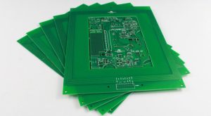
Mid-Frequency Ceramic Capacitor: Transition Layer Impedance Matching
The mid-frequency band, from 1 to 50 MHz, is a key transition area between bulk and high-frequency PCB capacitors. It needs to be filled by X7R or X5R multilayer ceramic capacitors, or MLCC, with capacitance from 0.47 to 10 microfarads. Such capacitors, with relatively low ESL, typically 2 to 5 nanohenries, and moderate ESR, 10 to 50 milliohms, can form a continuous low-impedance path between the frequency band where bulk capacitors fail, above their SRF, and the frequency band where high-frequency capacitors take effect, below their SRF. In terms of layout, mid-frequency capacitors must be directly connected across the VRM output and the main power plane, and use a vertical layer transition method of via-pad-via: top layer pad to inner layer power plane to bottom layer GND plane, avoiding thin wire routing. Measurements show that when the distance between a 10 microfarad MLCC and the VRM output exceeds 15 mm, its effective decoupling bandwidth will shrink by more than 30 percent. If single-point drilling is used instead of double-sided vias, the return path is lengthened, loop inductance increases, and impedance at 10 MHz rises by nearly 40 percent.
High-Frequency Ceramic Capacitor: The Ultimate Barrier at IC Power Pins
High-frequency decoupling, from above 50 MHz to GHz, completely relies on small-size, low-ESL MLCC in 0201 or 0402 packages, with capacitance from 0.01 to 0.1 microfarads. The core of its design is to minimize loop inductance. At this time, the capacitor’s own ESL, often less than 0.3 nanohenries, is much smaller than the parasitic inductance introduced by PCB routing, typically 0.5 to 2 nanohenries. Therefore, layout priority is higher than selection. The correct approach is to place the capacitor pads directly below or immediately adjacent to the IC power and ground pads, with a spacing of 200 micrometers or less, and connect them to inner layer power and ground planes through the shortest path micro vias, or via-in-pad. For example, in a six-layer board, it is recommended to place high-frequency capacitors on the top layer. Their power pads are directly connected to the second layer VCC plane through 0.2 mm diameter vias, and ground pads are directly connected to the third layer GND plane through another via. The center distance between the two vias should be 300 micrometers or less. This structure can control total loop inductance within 0.4 nanohenries, ensuring impedance remains below 20 milliohms at 500 MHz. If the traditional routing plus peripheral via method is used, loop inductance easily exceeds 1.5 nanohenries, causing impedance at 1 GHz to soar to the ohm level, completely losing high-frequency decoupling capability.
Power and Ground Plane Splitting and Reference Integrity
Decoupling effectiveness is highly dependent on complete reference planes. Any slot, narrow trace, or split in the power or ground plane will force high-frequency return paths to detour, greatly increasing loop inductance. Especially when the ground via of a high-frequency capacitor falls into a split GND area, the return current must cross the split gap, generating strong common-mode radiation. Practical requirements: the power and ground connections of all decoupling capacitors must be located in the same continuous plane area. If there are multiple power domains, such as 1.2 V Core and 3.3 V I/O, bridge capacitors should be set at the plane split. That is, place one 0.1 microfarad MLCC on each side of the split boundary, bridging adjacent power domains to provide a low-impedance return path for high-frequency noise. In addition, the number of vias between capacitor pads and planes must be sufficient. Each capacitor greater than 1 microfarad should have at least 2 ground vias, and capacitors greater than 10 microfarads need 4 or more, arranged symmetrically to balance current density.
Simulation Verification and Measurement Closed-Loop Optimization
Empirical layout can no longer meet the needs of process nodes below 28 nm. Full-link simulation must be combined. It is recommended to use three-dimensional electromagnetic field simulation tools, such as ANSYS HFSS or Cadence Sigrity PowerDC and PowerSI, to extract the Z-parameter model of the decoupling network. Focus on analyzing: first, the parallel impedance curve of each capacitor combination in the target frequency band; second, the position and amplitude of the PDN, or power delivery network, impedance peak at the IC power pads; third, the noise coupling strength near critical signal lines. In the measurement stage, a probe with a bandwidth above 20 GHz should be used to solder micro test points below the IC power balls to capture voltage fluctuation waveforms under synchronous switching events. If an obvious resonance valley, such as minus 30 dB, is observed near 200 MHz, it indicates a defect in the capacitance value or position of the mid-frequency capacitors. If noise above 1 GHz is not attenuated, the high-frequency capacitor ESL or layout has failed. At this time, adjust the capacitor type, package size, or re-plan the via topology, rather than blindly increasing the number of capacitors. Redundant capacitors may instead worsen high-frequency performance due to parallel resonance.
PCB Manufacturing Constraints and Reliability Collaborative Design
PCB Layout must take into account both design for manufacturability, or DFM, and long-term reliability. 0201 MLCC is sensitive to pad size. The IPC-7351 standard recommends pad length and width of 0.6 by 0.3 mm. If the design is too small, such as 0.5 by 0.25 mm, tombstoning is likely to occur during reflow soldering. If too large, excess solder paste will cause solder balls or bridging. At the same time, high-capacitance X7R capacitors have an obvious DC bias effect. Under rated voltage, their effective capacitance may attenuate by more than 60 percent. For example, a 10 microfarad 6.3 V X7R capacitor actually has only 4.2 microfarads of capacitance under 3.3 V bias. Therefore, when selecting, you must check the manufacturer’s DC bias curve according to the working voltage and reserve sufficient margin. For high-reliability scenarios such as automotive electronics, it is also necessary to avoid placing ceramic capacitors in areas of concentrated thermal stress, such as around BGA thermal pads, to prevent microcrack propagation failure caused by temperature cycling.
Gopcba provides professional PCB manufacturing, PCB assembly, prototype PCB assembly, low-volume PCB assembly, high-volume PCB assembly, SMT PCB assembly, through-hole PCB assembly, mixed-technology PCB assembly, flex PCB assembly, PCB design layout, components procurement, rapid PCBA prototyping, conformal coating, PCBA testing, box build assembly, wire cable harness assembly, medical PCBA, telecommunications PCBA, energy PCBA, industrial PCBA, artificial intelligence PCBA, Internet of Things PCBA, PCB capabilities, and PCBA capabilities. You can also visit our blog, learn about us, see why us, review our quality management, or contact us for more information.

