




DIP Inspection in PCBA: Through-Hole Quality Control Guide
DIP inspection in PCBA is the quality control step used after dual in-line package and other through-hole components are soldered. DIP boards contain connectors, transformers, relays, capacitors, and other parts with leads inserted through plated holes. The quality of these solder joints depends on hole fill, wetting, pin protrusion, and thermal control. Inspection must verify both the visible joint and the hidden connection inside the barrel because a weak through-hole joint can fail after thermal cycling or vibration.
This guide explains what DIP inspection checks, which methods are used, and how to control quality on mixed SMT and through-hole boards.
Through-hole soldering also creates a visible mechanical connection that may be stressed when a cable is connected or disconnected. A weak solder joint around a connector can develop a crack over time even when the electrical test at the factory passes.
Why DIP Inspection Is Important
Through-hole components are often used when mechanical strength, high current, or a reliable connector is needed. The solder joint must fill the barrel and connect the lead to the pad on both sides of the board.
A poor DIP joint may pass an initial electrical test but develop cracks during field use. Because many through-hole parts carry power or signals to other devices, failure can stop the whole product.
DIP inspection therefore protects reliability in industrial, medical, automotive, and power applications where a connector failure can interrupt critical equipment.
The board thickness and hole size affect the required solder volume. A thick board needs more solder to fill the barrel, while a small hole may be difficult to fill with a lead inside. The process should be designed with these factors in mind.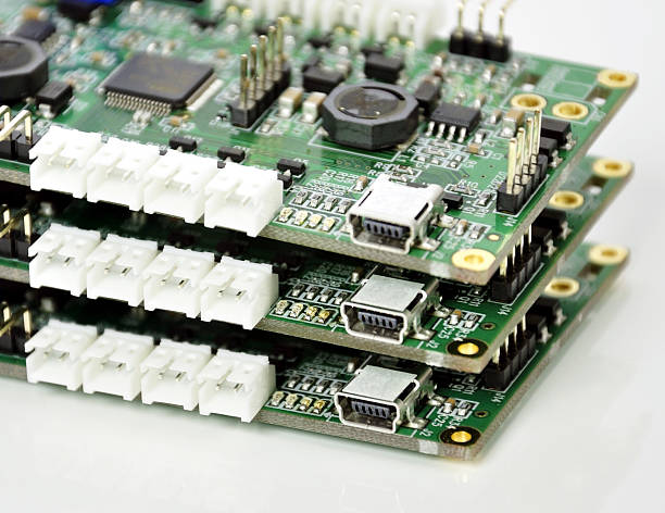
What DIP Inspection Checks
The first check is solder joint quality. The inspector verifies that solder fills the hole, wets the pad, and forms a smooth fillet without bridges, voids, or cold joints.
Component placement is also checked. Leads must be straight, inserted into the correct holes, and oriented with the correct polarity. Bent or lifted leads can create open connections.
Electrical performance is verified with test equipment after the visual and X-ray checks. The final result should show continuity and correct signal behavior.
Lighting and viewing angle are important for through-hole inspection. The inspector should view the fillet from the top and bottom, and compare the shape with accepted reference images. A shiny concave fillet usually indicates good wetting, while a dull or incomplete fillet may indicate cold soldering.
Visual Inspection of Through-Hole Joints
Visual inspection checks the top and bottom of the board. The top fillet should show that the lead was properly inserted, while the bottom fillet confirms that solder wetted the pad and formed a strong connection.
Common visual defects include insufficient solder, excess solder, solder balls, bridges between pins, cold joints, and disturbed joints caused by movement during cooling.
The inspector should follow the IPC-A-610 criteria for through-hole soldering and record the defect type and location.
AOI programs for DIP boards should include pin polarity, insertion depth, and spacing between leads. The system should be capable of distinguishing a valid through-hole fillet from surface solder that did not enter the hole.
AOI for DIP Boards
Automated optical inspection can be used after wave soldering or selective soldering to check component presence, pin alignment, solder fillets, and bridging. AOI is faster than manual inspection and suitable for repeated board layouts.
However, AOI cannot see inside the plated hole. It verifies the visible fillet but not the fill level inside the barrel.
For boards with a high risk of hidden hole defects, X-ray or microsection sampling should be added to the quality plan.
X-ray inspection can also be used to evaluate solder fill in plated holes with very high aspect ratios. If the solder only wets the pad surface, the barrel may contain no metal connection at all, creating an intermittent open circuit.
X-Ray for Hidden Through-Hole Joints
X-ray inspection can show whether solder filled the entire barrel or only formed a surface fillet. Incomplete fill can leave a weak connection that appears fine from the outside.
X-ray is especially useful for connectors and power components where the plated hole carries significant current or mechanical stress. It can also reveal voids and bridges that are hidden by the component body.
For high-reliability products, X-ray sampling should be defined in the quality plan based on process history and component risk.
Flux quality is another critical factor. The flux must remove oxide from the lead and pad, promote wetting, and leave residues that meet the product’s cleanliness requirement. Flux selection should match the solder and the board finish.
Wave and Selective Soldering Control
Wave soldering is used for many DIP boards because it can solder many through-hole joints at once. The process depends on conveyor speed, preheat, solder wave height, flux application, and board orientation.
Selective soldering is used when only some areas need through-hole soldering or when the board contains temperature-sensitive SMT components. It provides better control but lower throughput.
The soldering process should be qualified for each board and monitored with temperature measurements and inspection data.
Process monitoring should include solder temperature, wave contact time, and board temperature. A change in line speed or component loading can alter the amount of heat available to the joint and produce a different defect pattern.
Common DIP Defects and Causes
Bridges are caused by solder flowing between adjacent pins or pads. They may result from too much solder, insufficient spacing, poor flux, or incorrect board angle.
Insufficient hole fill can occur when the wave height is low, the board is too thick, or the hole diameter is too small for the solder to enter. Voids may be created by outgassing or poor flux coverage.
Cold joints and disturbed joints are caused by inadequate temperature or movement before the solder solidifies. Each defect has a different process cause and should be analyzed separately.
For high-current connectors, resistance measurement can identify a poorly filled hole before the board is installed. A high-resistance joint may pass a simple continuity test but still overheat under normal load.
Electrical and Functional Testing
After visual and X-ray inspection, the board should be electrically tested. ICT can verify continuity through the through-hole joints, while functional testing confirms that the assembled board works under real operating conditions.
For connectors and power paths, testing under load is important because a weak DIP joint may fail only when current flows.
Test records should identify the board serial number so any later failure can be traced back to the soldering and inspection data.
Board design should also make DIP inspection easier. Clear pin numbering, accessible test points, and adequate spacing between leads help the inspector and test system see and measure the joints without unnecessary handling.
Mixed SMT and DIP Assembly
Many boards combine SMT components with through-hole parts. The assembly order must protect SMT components from the heat of wave soldering. In some cases, SMT parts are placed and reflowed first, then through-hole components are added with selective or wave soldering.
The inspection plan must cover both technologies. SMT joints are checked with AOI and X-ray for hidden packages, while DIP joints require fill, wetting, and mechanical checks.
A reliable through-hole PCB assembly service uses a process matched to the board’s component mix.
The supplier should also document first-pass yield for DIP processes. If the yield is low, inspection alone will not solve the problem; the soldering equipment, stencil or flux settings, and component quality should be reviewed.
How DIP Inspection Reduces Cost
Catching DIP defects before functional test reduces rework and prevents expensive boards from being discarded. If a defective connector is found after assembly, replacing it can damage the surrounding board.
Consistent inspection also reduces the risk of field failures. A board that fails after installation may cost many times more than the original assembly price.
The quality process should combine visual inspection, AOI, X-ray, and testing without adding unnecessary delay to production.
It is also useful to review past DIP inspection data, such as common defect codes, repair rates, and the actions taken to correct them. This shows whether the supplier improves over time or simply repeats the same process.
Choosing a DIP Quality Partner
Ask the supplier how it controls wave and selective soldering, what inspection equipment it uses for through-hole joints, and how DIP failures are analyzed. A partner with both SMT and DIP experience can plan the process correctly.
For complete reliability, combine DIP inspection with SMT PCB assembly, PCBA testing, and controlled PCB manufacturing under one quality system.
DIP inspection should be part of a controlled process, not only a final sorting activity. The soldering equipment must be maintained, the profile validated, and the inspection criteria agreed with the customer before production begins.
Conclusion
DIP inspection in PCBA is essential for products that rely on through-hole connectors, power components, and mechanically strong joints. Visual review, AOI, X-ray, and electrical test each provide different information.
By combining process control with thorough inspection, a manufacturer can prevent hidden DIP defects and deliver reliable mixed-technology assemblies.


