Disturbed Joint: Movement While Solder Solidifies
A disturbed joint is one that was mechanically moved while the alloy was still partly liquid, so the surface has frozen in a rippled, grainy or stepped condition instead of the smooth concave shape a good fillet should have.
The defect is created in the seconds after the solder has solidified superficially but before it has gained strength. Anything that moves the board, the component or the joint in that interval leaves a permanent record of the movement on the joint surface.
What a Disturbed Joint Looks Like
The classic appearance is a rough, dull surface with concentric ripples or a step where the alloy was pushed aside and then froze. The joint may also show a crack around its base where the movement exceeded what the partly solid alloy could accommodate.
The defect is easiest to see with low angle lighting, because the surface texture causes it to scatter light differently from the surrounding joints. A joint that looks acceptable in a photograph taken from above often shows the disturbance clearly when the light is placed almost parallel to the board. The mechanism is related to the one behind a cold joint, but the cause is mechanical rather than thermal.
The Solidification Window
Lead free alloys do not freeze at a single temperature. SAC305 begins to solidify at about 217 C and completes over a pasty range of a few degrees, during which the joint is a mixture of solid and liquid and has very little strength.
The window that matters is the interval from the moment the joint surface skins over to the moment the whole joint is solid, which on a typical assembly lasts a fraction of a second to a few seconds depending on joint mass. Movement in that interval, not later, is what creates the defect.
Vibration and Handling Sources
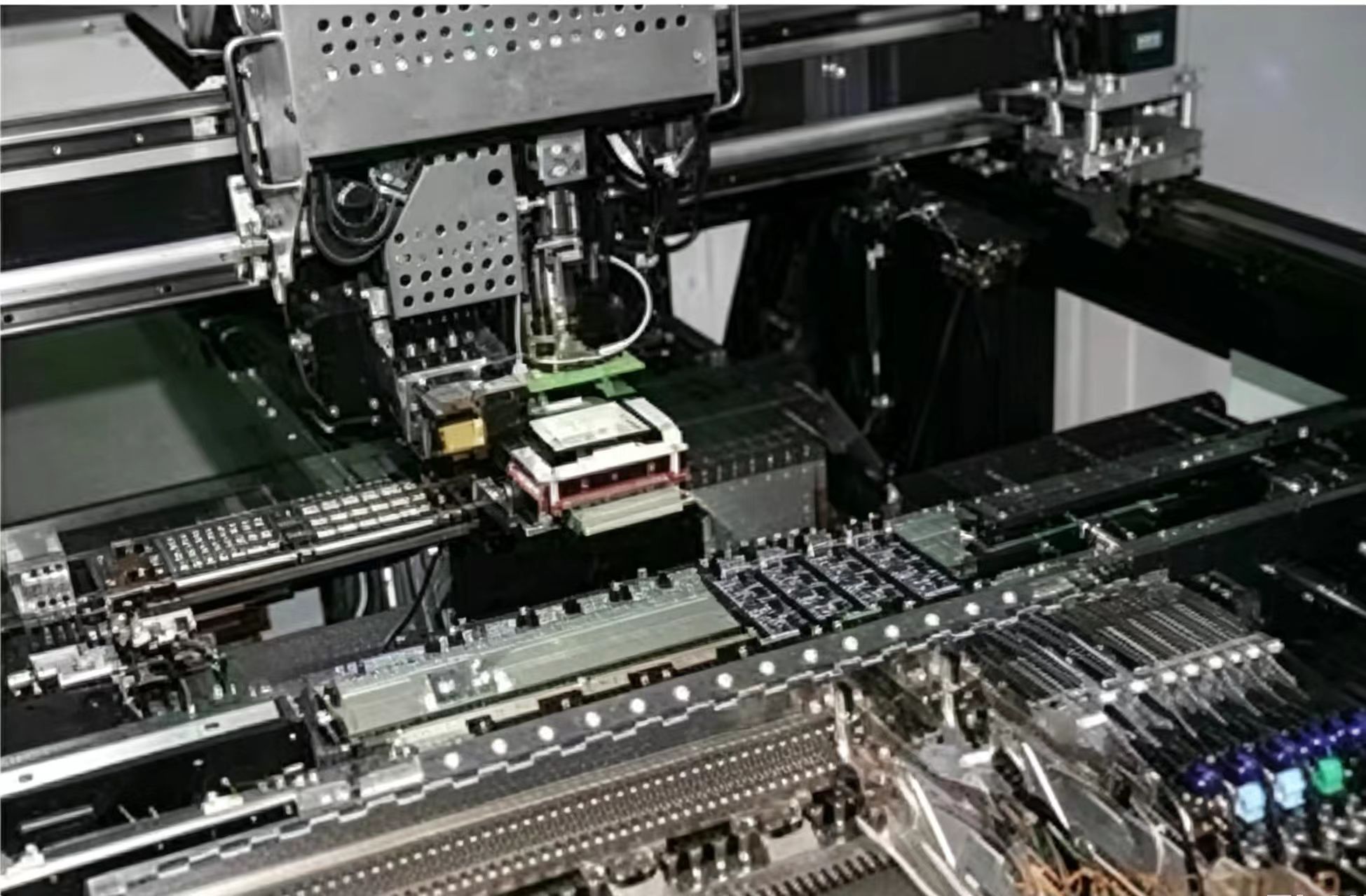
Conveyor vibration is the most common source. Rollers that are out of round, a drive chain with a tight link, or a belt that has developed a flat spot all transmit a periodic movement into the board while the joints are cooling on the exit end of the machine.
Handling adds to it. A board that is picked up while still warm, or one that is dropped onto a stack, can disturb joints that have not yet fully solidified. Boats, pallets and carriers that rattle on the return conveyor contribute in the same way, and the effect is usually seen as a band of disturbed joints at one position on the panel. A simple check is to stand a coin on the board as it leaves the machine: if the coin rattles, the conveyor is passing vibration into the assembly at the moment the joints are setting. Conveyor behaviour is central to this class of defect, as the notes on conveyor vibration control explain.
Drafts, Fans and Uneven Cooling
Air movement does not move the joint directly, but it does change the cooling rate. A fan that blows onto one part of the board cools that region faster, and the resulting temperature gradient across the assembly produces differential contraction that can move a joint while its neighbours are already solid.
The same effect appears when a board leaves the oven with one end in the cooling zone while the other is still in the last heated zone. The remedy is to check the cooling arrangement rather than the alloy, and to confirm that the board is not being cooled so quickly that it bows.
Component and Package Contributions
Heavy components have more thermal mass, so their joints stay liquid longer and are exposed to movement for longer. A large transformer or a connector body that is not supported during soldering can settle under gravity at exactly the wrong moment.
Flexible leads add another path. A lead that is pre loaded, either by a bend introduced during insertion or by its own rigidity, will move the joint as the board changes dimension during cooling. Components should be seated without stress and, where the mass requires it, held in place until the joints have solidified.
Effect on Joint Strength
A disturbed joint has a disrupted grain structure and a rough surface, and the surface irregularity is often accompanied by internal porosity where the movement trapped shrinkage voids. Both reduce fatigue life, and the effect is larger under thermal cycling than under static load.
The defect does not always produce an immediate functional failure, which is what makes it dangerous. A joint that passes continuity test can fail after a few hundred thermal cycles, and the failure will be attributed to a design or material issue unless the disturbance was recorded at the time of manufacture. The loss of strength is greatest in alloys with a wide pasty range, which is one reason lead free assemblies are more sensitive to disturbance than the tin lead alloys they replaced.

Detection and Inspection
Visual inspection with oblique lighting finds the obvious cases. Automatic optical inspection finds them less reliably, because the criteria are surface texture rather than geometric, and the algorithms that measure fillet shape are not always tuned to detect roughness.
X-ray adds little for this defect, since the disturbance is a surface and grain feature rather than a void pattern. The most effective control is therefore a defined visual check at the exit of the soldering machine, carried out by an inspector who knows which surface appearance indicates movement.
Process Fixes
Fixes are mechanical first. Check the conveyor for out of round rollers, worn bearings and belt damage, and confirm that the board is fully supported as it leaves the heating zones. A board that overhangs the end of the conveyor with no support will droop as it cools. Support rails should extend far enough beyond the last heated zone that the joints have solidified before the board is unsupported.
Second, slow the cooling if the alloy is being frozen too quickly for the mass of the joint, and remove any source of air movement that targets one area of the board. Third, review handling after the machine so that boards are not moved until they are cool enough to be rigid.
Records and Acceptance
Acceptance criteria for a disturbed joint come from the applicable workmanship standard, and in most classes the defect is not permitted on a joint that carries structural or thermal load. The record should note where on the panel the disturbed joints were found, because a band across one position points to a mechanical cause and a scattered pattern points to handling.
Where a batch has been affected, the decision to rework or scrap should consider how much of the joint is involved. A surface disturbance with no cracking can sometimes be accepted after evaluation on a sample, while a joint with a circumferential crack at its base should be removed and re soldered. The final check after rework is the same visual routine used at the machine, as described in the optical inspection practice for the line.
FAQ
What causes a disturbed solder joint? Movement of the board, component or joint while the alloy is between the liquidus and full solidification. Conveyor vibration, drafts, unsupported heavy parts and handling of warm boards are the usual sources.
Is a disturbed joint always a reject? Acceptance depends on the product class and on the extent of the disturbance. A joint with a circumferential crack or internal porosity should be reworked, while a light surface ripple may be evaluated against the standard.
Can a disturbed joint be detected by X-ray? Not reliably. The defect is a surface texture and grain structure condition, and X-ray is better at finding voids and missing solder than at revealing movement during solidification.
}