
Drill Accuracy on a PCB Line: 6 Checks Before a Tight Job
Drill accuracy is the ability of a machine to place a hole where the program says it should be, and to do it the same way on every panel. It is not one property but the sum of several: spindle condition, tool holder, tooling and clamping, the entry layer, and the drill bit itself.
When a job has a tight position tolerance, those factors have to be checked before the run rather than diagnosed afterwards. A machine that has drifted half a thousandth of an inch will still produce good boards on a loose design, and will quietly fail a tight one. That is why the checks belong before the job, when the machine can still be corrected without scrapping a lot.
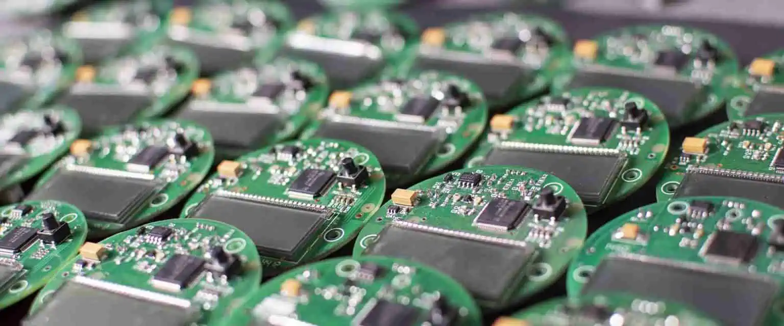
<img src="https://www.gopcba.com/wp-content/uploads/2026/09/43-2.jpg" alt="Drill machine spindle and tool holder checked for spindle runout before a PCB job” />
What Drill Accuracy Covers
Accuracy is usually split into position accuracy and repeatability. Position accuracy is how close the hole lands to its nominal location, while repeatability is how closely successive panels match each other. A machine can be repeatable but offset, which is detectable and correctable, or accurate on average but inconsistent, which is not.
Both matter for the same reason. Every hole has to finish inside its pad or its annular ring, and the budget for error is shared between the drill, the registration of the artwork and the drill position the fabricator is given.
Position Tolerance and the Error Budget
The error budget for a hole is finite. Part of it is consumed by layer to layer hole registration from the imaging and lamination steps, part by the drill machine position, part by panel movement during drilling and part by drill wander inside the material.
Where the design uses a minimum annular ring, the drill allowance is usually the smallest share and the easiest to control. That is why a job with tight rings should start with a machine accuracy check, since it is the only item in the budget that can be verified independently of the panels, using a coupon rather than a production board.
Spindle Runout and Tool Holder Condition
Spindle runout is the wobble of the rotating tool about its axis. It comes from the spindle bearing, from a worn collet or from a tool holder that has been damaged by a broken drill, and it causes the hole to be larger than the tool and less round than it should be.
Runout also shortens drill life and worsens hole quality on small tools, because each flute engages unevenly. Measuring runout with a dial indicator on a test pin is a quick check, and a reading above the machine specification is a reason to stop the job rather than to add a compensation offset, which would hide the wear and leave the hole geometry wrong.
Tooling, Clamping and Panel Movement
The panel has to stay still while it is drilled. Tooling pins locate it, clamps hold it, and the drill table moves the stack underneath. Any looseness between these parts appears as a hole that is positioned differently from one end of the panel to the other rather than as a random scatter.
Tooling holes that are worn, or that were drilled undersize, allow the panel to sit fractionally differently each time it is loaded. Checking the tooling holes for wear and confirming a snug fit on the pins is part of machine setup rather than a maintenance detail that can wait until the next service.
Entry Material and Its Effect on Wander
The drill tip can wander in the first moments of contact, especially on a small tool entering a smooth surface. A rigid entry material holds the copper and the laminate down and guides the tip, which reduces both wander and the top-side burr.
Entry material also affects the temperature the resin sees. A lubricated layer reduces friction at the tip, so the resin is less likely to soften and smear, and a softer drill entry produces holes that are more consistent in size across the stack.
Chip Load, Feed and Drill Wear
Chip load is the thickness of material removed by each cutting edge per revolution. Too small and the edge rubs instead of cutting, generating heat and wearing quickly; too large and the drill deflects, which moves the hole away from the program position.
Wear changes both. A worn drill cuts a smaller hole and tends to deflect more, so the effective position accuracy of a stack degrades through the life of the bit. Recording hits per bit and replacing on a defined count is the simplest way to keep this variable inside the budget, and the drill bit selection rules set the starting point.
Verifying Accuracy With a Test Coupon
A drill test coupon carries a pattern of holes that can be measured optically against their nominal positions. The measurement gives a distribution rather than a single figure, and the distribution shows whether the error is a constant offset, a scale error across the panel or a random scatter.
Running the coupon before a tight job, and again afterwards, brackets the production run with evidence. Where the result changes between the two runs, the machine or the tooling moved during production, which is exactly the case an offset compensation would hide.
When the Error Is Registration, Not Drilling
Not every position problem comes from the drill. If holes are accurately placed relative to each other but consistently offset relative to the inner layers, the cause is in the imaging or the lamination step rather than in the machine, and correcting the drill would move every hole away from the copper it has to connect.
The distinction is easy to make with the coupon data and the registration targets on the panel. Comparing the hole to hole measurement with the layer to layer measurement tells you which budget item is consuming the tolerance, and it prevents a machine adjustment that makes the actual defect worse.
Building a Drill Quality Record
A simple record of runout, tooling condition, chip load setting, hits per bit and coupon results gives the shop a history for each machine. Over time that history shows which machine drifts, which maintenance action actually corrects it and how long a correction lasts.
That record also supports the process where it counts. A hole that fails an annular ring check, a cracked barrel after thermal cycling or a rough hole wall all invite a search through the drilling parameters, and having the data already available removes most of the guesswork. Where the aspect ratio is high, the same record should be reviewed against the aspect ratio limits for the bit and the machine, since a hole that is difficult to drill is also difficult to plate.
FAQ
How is spindle runout measured? A dial indicator is set against a test pin held in the spindle and the spindle is rotated by hand, reading the total indicated movement. The check takes a few minutes and should be repeated after any broken tool or tool holder change.
Can drill position be corrected with an offset? A constant offset can be compensated in the program, but the correction has to be based on coupon data and re-verified afterwards. Compensating for a random scatter with an offset simply moves the errors instead of removing them.
Does entry material affect hole position? It affects wander at the point of entry, which is part of the position error on small holes. A rigid, lubricated entry layer guides the tip and reduces that contribution, particularly in a tall stack where the drill is least stiff.