E-Paper Display Driver Circuit Design
An e-paper display holds its image without power, which makes it ideal for a battery powered label or a status panel. The trade is that the image is written with a high voltage waveform applied for a defined period, so the driver circuit is a small power supply and a timing controller rather than a simple level shifter.
How an E Paper Display Works
Microscopic capsules or microcups contain charged pigment particles suspended in a fluid. Applying an electric field moves the white particles to one surface and the black to the other, and the image is formed by controlling the field across each pixel. Once the field is removed the particles stay where they are, which is why the display holds its image with no power.
The field is produced by the difference between the pixel electrode and the common electrode, and the voltages required are much higher than the logic supply, typically between ten and twenty volts and sometimes more. That is the reason for the charge pump: the panel needs a voltage that no single cell can supply directly.
The polarity of the field determines which particles come to the surface, so the driving waveform alternates between positive and negative pulses. The sequence and duration of those pulses is the waveform, and it is specific to the panel type and to the temperature.
The High Voltage Requirement
The panel datasheet specifies the maximum voltage that may be applied and the gate drive levels for the row selection. Exceeding the maximum changes the behaviour of the particles permanently, which appears as a panel that no longer reaches full black or full white, so the supply has to be regulated with margin and monitored.
The current requirement is modest but not negligible. Charging the capacitance of a large panel takes a pulse of current at every transition of the waveform, and the average current is the product of the panel capacitance, the voltage swing and the refresh rate. A design that supplies the correct voltage but not the required pulse current will produce an image that is weak or uneven.
Both polarities are needed for the waveform, so the typical arrangement is a positive rail, a negative rail or a ground referenced bipolar drive, and a set of level shifters that connect the panel electrodes to whichever rail the waveform requires.
Charge Pump and Supply Design
charge pump generates a higher voltage from a lower one by switching capacitors, and it is used because it needs no inductor and produces little noise. Multiple stages multiply the input voltage, and the achievable output depends on the number of stages, the switching frequency and the load current.
The output impedance of a charge pump rises as the number of stages increases, so a design that needs a high voltage at a significant current requires either a larger flying capacitor or a different topology. A switched inductor boost converter is more efficient at higher currents and is used where the panel is large or the refresh rate is high.
Regulation is usually achieved by monitoring the output and adjusting the switching, with a reservoir capacitor that supplies the pulse current during each waveform transition. The capacitor has to be large enough to hold the voltage during the refresh, and the general placement rules for a reservoir capacitor are described in bulk capacitor placement.
Waveform and Refresh Time
waveform is a sequence of voltage pulses applied to the panel, and it is supplied by the driver as a table of frames. The sequence begins with a clearing phase that resets the particles, followed by the phases that write the new image, and it ends with a settling phase. The whole sequence is the refresh time, which ranges from a fraction of a second to several seconds depending on the panel and the mode.
refresh time is the parameter that most affects the user experience. A full refresh that flashes the screen several times is acceptable for a page change on a reader and unacceptable for a status indicator that updates frequently. Partial refresh modes write a smaller region with fewer phases, at the cost of a less complete reset and a gradual accumulation of ghosting.
The waveform is temperature dependent. The viscosity of the fluid rises at low temperature, so the particles move more slowly and the pulses have to be longer, while at high temperature the pulses can be shorter. Using a single waveform at all temperatures produces an image that is too light in the cold and over driven in the heat.
Ghosting and Partial Refresh
ghosting is the faint trace of a previous image that remains after a new one is written. It happens when the clearing phase does not fully reset the particles, and it accumulates over a series of partial refreshes until a full refresh is performed to clear it.
The accumulation is predictable, and most controllers count the partial refreshes and force a full one after a defined number. That number is a compromise between the visible quality of the display and the flashing that users find unpleasant, and it is worth tuning on the actual product rather than accepting the default.
Ghosting is also affected by the temperature and by the age of the panel. A panel that shows clean images when new may show traces after a few years of use, because the particle mobility changes slowly. Keeping margin in the waveform rather than running at the minimum voltage extends the useful life of the display.
Temperature and Refresh Behaviour
The panel needs a temperature reading for two reasons: to select the correct waveform and to decide whether the display can be updated at all. Below a defined temperature the particles move so slowly that the update takes an unreasonable time, and some controllers refuse to refresh rather than produce a bad image.
The sensor should be attached to the panel rather than to the board, because the panel has a significant thermal mass and its temperature lags the electronics. A sensor on the board reads the driver temperature, which is usually higher, and using it would select a waveform that is too short for the actual panel.
Where the display operates outdoors, the temperature range can span sixty degrees, and the waveform table has to cover the whole span. Each entry in the table is verified by measuring the resulting contrast at that temperature, and the verification is repeated after the panel has been cycled, because the behaviour changes as the particles settle into their final distribution.
Interface and Layout
The interface between the controller and the panel is usually a serial bus for commands and data, with the high voltage drive provided by the panel itself or by an external driver. Several panels include the drive circuitry, in which case the board provides the supply rails, the level shifting and the timing signals.
Keep the high voltage rails away from the logic signals in the layout. The panel drive currents are pulsed, and the switching produces noise that couples easily into the serial bus and into the temperature sensor. The partition between the noisy supply area and the quiet logic area is the same one described in mixed signal board design.
The connector to the panel deserves attention, because the panel is a high impedance, capacitive load that is connected by a flexible cable. The cable carries both the high voltage drive and the logic signals, and separating them in the connector pinout reduces the coupling. The datasheet of the panel defines the pinout, but the assignment of the ground pins is still the designer choice and should place a return next to every signal group.
Verification and Common Faults
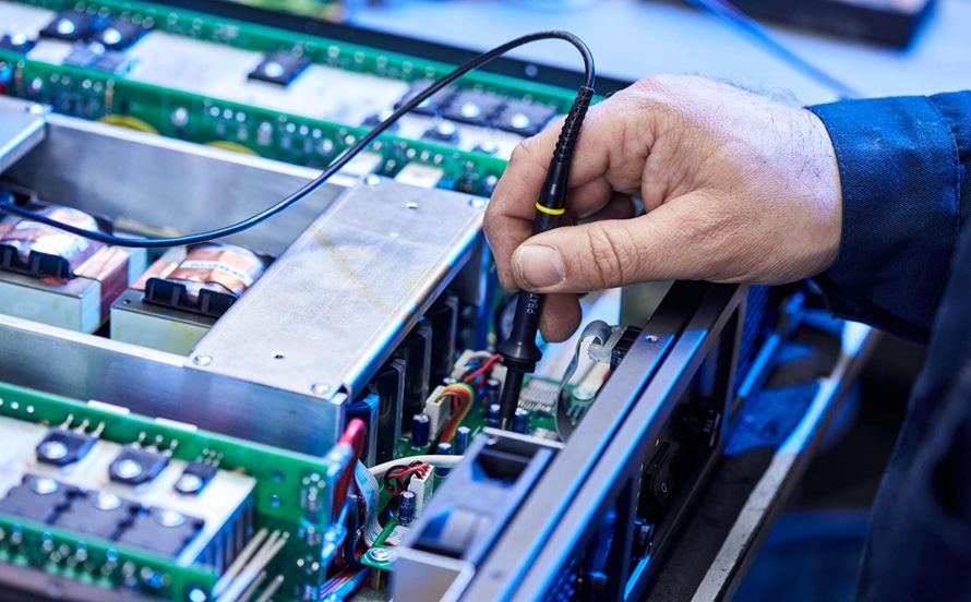
Verify the supply rails under load rather than open circuit, because a charge pump with a high output impedance may produce the correct voltage with no load and a much lower one during a refresh. Measuring the rail during the refresh with a scope shows the dip, and the fix is a larger reservoir capacitor or a lower impedance supply.
Verify the waveform by measuring the panel electrode signals during a refresh. The amplitude, the duration and the polarity of each phase should match the table, and any discrepancy points to a level shifter that is not driving properly or to a supply that is sagging.
An image that is uniformly too light usually indicates a supply voltage below the specification or a waveform that is too short for the temperature. An image with a gradient across it points to a distribution problem, either a voltage drop along the panel electrode or a drive strength that is insufficient at the far end. The release checks that record these parameters in the production documentation are described in PCB design release checklist.
FAQ
Why does my e-paper display need so much voltage? The pigment particles are moved by the electric field, and the field depends on the voltage across a small gap. The panel specification gives the voltage range that produces full contrast.
How often should a full refresh be performed? After a defined number of partial refreshes, typically between ten and fifty depending on the panel and on how much the image changes. The number is tuned to keep ghosting below the visible level.
Can I use a boost converter instead of a charge pump? Yes, and it is preferable at higher currents. A charge pump is simpler and quieter when the load is small, which is the usual case for a small panel.