Elevator Control Board EMC: PCB Design and Manufacturing
An elevator control board sits beside motors, drives and contactors that switch heavy currents many times a second. That environment decides how the board must be designed and built. EMC is not a test you add at the end of a project. It is a set of layout, stackup and process decisions made long before the first panel is etched. Each decision limits how much noise enters sensitive circuits and how much the board sends back out.
The control board receives commands, reads sensor signals, drives the motor interface, manages the door and talks to other subsystems. Every one of those functions carries a noise risk. Motor switching transients, variable-frequency drives, relay arcs and long power cables all couple energy into the board. Poor EMC shows up as communication errors, unstable sensor readings, processor resets or unexpected behavior. Buyers should treat EMC as a design and manufacturing property, not a certificate collected at the end.
Immunity and Emissions Together
Electromagnetic compatibility has two sides, and both matter on an elevator controller. Immunity means the board keeps working when external interference arrives. Emissions control means the board does not disturb other equipment nearby. A design that fixes one side can weaken the other if the return paths are not planned together. Engineers should review both goals at the same time during schematic and layout review.
Elevator cabinets are crowded. Control electronics share space with high-power motors, drives, relays, contactors and communication networks. The board must survive that environment and stay quiet enough for its neighbors. This is why the whole electrical system shapes the result, not just the PCB. Still, PCB architecture and fabrication quality have a large influence on what the final board can achieve in the field.
Conducted and Radiated Noise
Motor drives and switching supplies push high-frequency noise onto power and signal lines. Without filtering and a solid ground structure, that noise enters sensitive circuits through connectors and rails. The usual symptoms are microcontroller resets, communication faults, sensor drift and false signal detection. Power-entry filtering, local decoupling and short return paths reduce the risk. Each fix works best when placed close to the source or the entry point it protects.
Long motor cables, encoder lines and power wiring can act as antennas. They couple energy into the board and also radiate what the board generates. Fast switching nodes and high-speed digital signals add to this when their current loops are large. Compact loops and continuous reference planes shrink the antenna effect. A designer who controls loop area early avoids expensive shielding later in the project.
Functional Zoning and Placement
Divide the board into clear regions before routing begins. Power entry and protection, motor interface, digital control, analog sensing, communication ports and safety circuits each need their own space. High-noise switching circuits should sit away from low-level analog and communication circuitry. Sensitive parts such as converters, sensor amplifiers, oscillators and transceivers deserve placement that considers their electromagnetic surroundings. Zoning is a planning step, and it is hard to correct once copper is poured. For sourcing checks on those parts, see our component procurement notes.
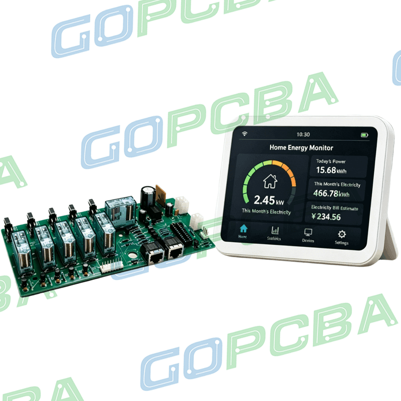
Placement should also shrink high-frequency current loops. Decoupling capacitors belong close to the IC power pins with short connections to power and ground. Filter components belong near the interface or noise source they control. This discipline keeps noise from spreading across the board. A structured PCB design and layout review can catch EMC and manufacturability risks before production starts. Reviewers should check placement against the schematic functions, not just against the mechanical outline.
Routing and Reference Planes
Motor-control and switching circuits carry rapidly changing currents. Keep those loops as compact as practical to cut parasitic inductance and radiated emissions. High-speed traces need a continuous reference plane underneath. A split or interrupted return path raises loop area and creates radiation. Multilayer construction gives dedicated power and ground planes, which improves return-current control and separates noisy circuits from sensitive ones. The routing review should trace each return current back to its source.
Differential signaling improves immunity to common-mode interference when it is done correctly. Encoder signals and communication links should follow the interface requirements for pair geometry, spacing and reference continuity. Vias and connector transitions affect signal integrity as much as the trace does. Differential routing does not remove EMI on its own. The complete path and the common-mode behavior still need attention. Where impedance control is required, trace width, copper thickness and dielectric spacing form one transmission-line structure with a target set by the interface specification.
Grounding and Interface Filtering
Grounding is often misunderstood. In a modern multilayer board, a solid ground plane usually gives a lower-impedance and more predictable return path than long discrete traces. It cuts return inductance, reduces loop area and limits unwanted coupling. Splitting the plane into isolated islands is not automatically better. The grounding plan should follow current paths, circuit functions and isolation needs. High-current switching returns must not share sensitive signal return paths in ways that create voltage drops or common impedance coupling.
Connectors are natural entry and exit points for interference. Power inputs, motor interfaces, encoder links and communication ports may need common-mode chokes, ferrite parts, transient protection or RC filtering. Filter selection must match operating frequency, signal bandwidth, current, voltage and impedance. A poorly chosen filter can add attenuation, resonance or insertion loss to a working signal. Shielding may be needed near powerful switching equipment. A metal cover only works when it connects properly to the chassis and its seams and cable entries are handled.
Stackup, Materials and Fabrication
Material choice affects signal integrity and long-term reliability. Standard FR-4 suits many elevator controller designs. More demanding boards may need higher-Tg materials or low-loss laminates, depending on temperature, signal speed, layer count and reliability targets. The stackup should be settled with signal layers, ground planes, power planes, dielectric thickness, copper thickness, impedance targets and thermal needs in view. Complete stackup work before detailed routing, because later changes ripple through the whole design.
Good EMC can be lost to process variation. Copper thickness affects resistance, current capacity and impedance. Dielectric thickness between a signal layer and its reference sets characteristic impedance and field spread. Etch accuracy controls trace width, which matters most on high-speed nets. Layer registration keeps the intended geometry, and via design shapes signal transitions and return paths. A controlled quality management system should include engineering review and manufacturability analysis before fabrication begins. Buyers should confirm which parameters are measured and which are only assumed.
Validation and Prototype Builds
EMC is validated at PCB and system level. Depending on the product and market, testing may cover conducted and radiated emissions, electrostatic discharge, fast transients, surge, radiated and conducted RF immunity, magnetic-field immunity and voltage dips. The exact list follows the equipment classification, the applicable standards and the full system configuration. Board inspection with AOI, electrical test, X-ray and impedance checks supports this work. Inspection alone never replaces system-level EMC testing, and a passing bare board says little about cabinet behavior.
Prototype builds are the cheapest place to find EMC problems. A pilot batch can evaluate layout, grounding, filter performance, communication stability, sensor behavior, motor-drive interfaces and thermal margins. Teams can then change the PCB before tooling and certification lock the design. rapid PCBA prototyping shortens that loop and keeps the schedule intact. Component sourcing should also be fixed early, since a substitute part can change filtering or timing. For volume programs, high-volume PCB assembly should keep the same process and documentation used in the pilot.
Fabrication and assembly records matter as much as the hardware. The factory should record which program ran, which materials were used and what inspection found. When a field return appears months afterward, that record is the fastest way to identify the cause. Buyers should ask for process documentation, inspection data and test reports as a routine part of every order. A supplier that reviews files before production and reports risks honestly is usually cheaper over the life of the product than one that quotes low and surprises later.
The practical takeaway is simple. Fix EMC in the layout, stackup and process plan, then prove it on a prototype before committing to volume. Ask the supplier which parameters are controlled, which are measured and which records travel with each lot. Those answers tell you more about elevator control board EMC than any brochure claim.