Fine Pitch Stencil Aperture Design at 0.4 mm
At a fine pitch the printing process stops being a way of applying paste and starts being a contest between two surfaces. Each deposit is a fraction of a cubic millimetre, and whether it ends up on the pad or stays on the aperture wall decides the joint. This article covers the geometry, the materials and the machine settings that decide the outcome, and the measurements that show which one is limiting the process.
Why Fine Pitch Changes the Print
At a 0.4 mm pitch the pad is roughly 0.2 mm wide and half a millimetre long, so a deposit is on the order of 0.1 cubic millimetre of paste. At that volume the adhesion of the paste to the aperture wall is comparable with its adhesion to the pad, and the weaker surface loses.
Everything that helps at coarse pitch helps more here: a thinner stencil, a smoother wall, a lower separation speed and a finer powder. None of them is sufficient alone once the area ratio falls below about 0.6, because the geometry then dominates every other setting.
Area Ratio and Transfer Efficiency
Area ratio is the aperture opening area divided by the area of the wall that the paste has to slide against, and it is the best single predictor of release. Below 0.66 the transfer becomes sensitive to everything else, and below 0.5 the deposit is unreliable whatever the printer does.
Transfer efficiency is the deposited volume divided by the aperture volume, and it is measured rather than assumed. A process running at 85 percent at a 0.4 mm pitch is doing well, and one at 60 percent is producing joints short of alloy without any visible print defect. The measurement methods are described in our SPI guide.
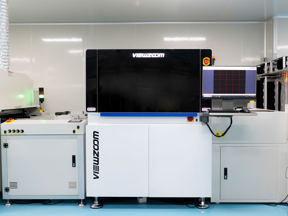
Transfer efficiency is reported per aperture, which is the useful view at fine pitch because the failure mode is a few weak apertures rather than a uniform shift.
Stencil Thickness and Aspect Ratio
Thickness trades area ratio against volume. A 0.10 mm stencil raises the area ratio and delivers less paste, while 0.12 mm delivers more and risks the release. The choice follows from the joint volume the design requires rather than from habit.
Aspect ratio, the aperture width divided by the stencil thickness, should stay above 1.5. A 0.2 mm wide aperture in a 0.12 mm stencil gives 1.67, which works but leaves no room for the narrower aperture that another device on the same board may need.
Aperture Geometry and Wall Finish
Laser cut apertures have a tapered wall and a rougher surface than electroformed ones, which changes the release. Where the board is dominated by fine pitch, an electroformed or nickel plated stencil with polished walls transfers more paste at the same area ratio.
Shape matters at the corners as well. A rounded rectangle releases more evenly than a sharp one, and a small extension at the outer end of the pad adds paste where the fillet forms. Both changes live in the stencil file and neither touches the copper.
Aperture Reduction and Paste Volume
Apertures are normally reduced relative to the pad to prevent bridging, typically to 80 or 90 percent of the pad area. At fine pitch that reduction is what keeps the paste on the pad, but it also removes volume that the joint needs.
The reduction is set from the measured bridging rate and the target joint volume rather than from a general rule. Where the print is stable, a smaller reduction puts more alloy in the joint; where it is not, the reduction conceals a problem that will show up at another pitch. The volume side is covered in our paste volume guide.
Paste Powder Size and Rheology
Powder grade defines the largest particle in the paste, and the particle has to pass the aperture without bridging. A type 4 paste, with particles up to about 20 micrometres, suits a 0.2 mm aperture, and type 5 or 6 is used below that.
Rheology matters as much: paste that is too viscous does not fill the aperture corners, and paste that is too thin slumps after release. Metal content also changes the deposit, because a higher metal load leaves less flux to escape and holds a firmer printed shape.

Powder grade and aperture size are matched on paper before the paste is ordered, because a paste that bridges at one aperture size will do so at every aperture of that width on the board.
Separation and Support
Separation speed is the setting most often left at its default, and at fine pitch it decides whether the paste shears off the wall or is torn from it. A two stage separation, slow for the first fraction of a millimetre and faster afterwards, improves transfer noticeably.
Support under the board is denser than at coarse pitch, because a board that flexes during the print changes the gap between stencil and pad locally. Pins on a 25 mm pitch under the fine pitch area are common, with the pattern checked against the bottom side layout.
Inspection and Feedback
At fine pitch the deposit is measured per aperture rather than sampled, because the failure mode is a small number of low volume deposits rather than a uniform shift across the board. Inspection reports volume, area and height for each opening.
That output feeds back to the print settings and to the stencil design, which is why the measurement is taken on the production board. A coupon with different aperture sizes does not describe the release the product actually sees.
Design and Documentation
The stencil drawing should state the thickness, the aperture size relative to the pad, the area ratio of the smallest aperture, the wall finish and the paste type assumed. Those five items define the print, and changing one changes the others.
Where the area ratio cannot be met, the usual answers are a thinner stencil with a smaller fillet or a stepped stencil that thins only over the fine pitch device. The stepped option belongs on the drawing rather than in a note added after the first build. Placement of the parts concerned is discussed in our capability notes.
The paste release from an aperture depends on the wall angle as much as on the area ratio, because a tapered wall presents a smaller contact area at the pad surface and lets the deposit shear away progressively. A stencil cut with a five degree taper releases better than one with a straight wall at the same nominal size. Where the supplier offers the choice, the taper is specified rather than left to the process.
A step stencil resolves the conflict on a board that carries both a fine pitch device and a connector needing a thick deposit. The step is formed by thinning the foil locally, and the transition has to fall where there are no apertures, because paste behaves differently at the boundary. The step position belongs on the stencil drawing rather than in an adjustment made at the printer.
Nano coatings applied to the foil reduce friction between paste and wall and improve release without changing the geometry. The coating wears with cleaning, so its effect is verified rather than assumed, and a stencil cleaned aggressively loses the coating long before the apertures wear.
Squeegee pressure at fine pitch is set to the low end of the usable range, because excess pressure drives the foil into the board and squeezes paste under the stencil between apertures. The setting to keep is the one that gives the most consistent deposit volume rather than the highest, and it is recorded with the recipe.
The under stencil wipe is run more often at fine pitch, because a small deposit of paste on the foil underside transfers to the mask of the next board and appears later as a bead beside a pad. A vacuum wipe with solvent assist is used where the paste skins over quickly on the foil.
Ambient conditions affect the print more at fine pitch than at coarse, because a small deposit loses its solvent within minutes. The print room is held near 23 degrees Celsius and 45 to 55 percent relative humidity, and the printer enclosure is closed rather than open to the aisle.
FAQ
What area ratio should be the minimum? Keep above 0.66 for a stable process and treat anything below 0.6 as a design discussion rather than a printing challenge.
Is a thinner stencil always better at fine pitch? It improves release but reduces the volume, so the stencil thickness follows from the joint volume the design needs.
Why does transfer efficiency matter more than deposit height? Because the joint is formed from the volume, and a deposit of the right height with too small an area is still short of alloy.