The Difference Is Not the Layer Count
Engineers comparing quotations for a high-density interconnect board and an ordinary multilayer board often conclude that the HDI version is simply more expensive for the same number of layers. The comparison is misleading, because the two constructions differ in how connections are made rather than in how many layers they contain.
A conventional multilayer board uses plated through holes that pass from the top surface to the bottom. Every hole consumes routing area on every layer it crosses, and the area it occupies cannot be used for signal routing. As layer count rises, the accumulated cost of those blocked areas becomes the dominant constraint on how much can be routed.
First-order HDI changes that by introducing blind vias that connect the outer layer to the first inner layer only. Because the via stops before passing through the whole board, the layers beneath remain available for routing. That single structural change is what produces the density advantage, and understanding it is the key to deciding when HDI is worth its cost.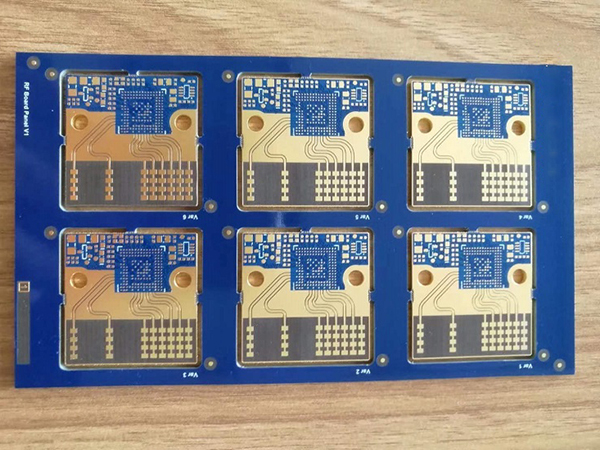
How a Blind Via Frees the Stack
The mechanism is straightforward geometry. A through hole occupies a pad on every layer, and the clearance around that pad removes routing space. A blind via occupies a pad only on the two layers it connects, so inner layers that would otherwise be perforated remain continuous.
On a board that needs to escape a fine-pitch device, this is often decisive. The escape region is where routing channels are scarcest, and freeing even one inner layer in that area can remove the need for two additional layers elsewhere. That is why a first-order HDI board with fewer layers can sometimes replace a thicker conventional board while improving electrical performance.
There is an electrical benefit as well. A blind via that does not penetrate the whole board avoids the stub that a through hole leaves below the connection point. At high frequency a stub behaves as a resonator, degrading the signal. Removing it improves insertion loss and reduces reflection, which matters increasingly as data rates rise.
There is a second-order benefit that deserves mention: panel utilisation. Because HDI allows a smaller outline for the same function, more boards fit on a standard production panel, which reduces material cost per board and can partially offset the added process cost. Programmes that evaluate only the fabrication price per square metre miss this effect, which is often significant on small, high-volume boards.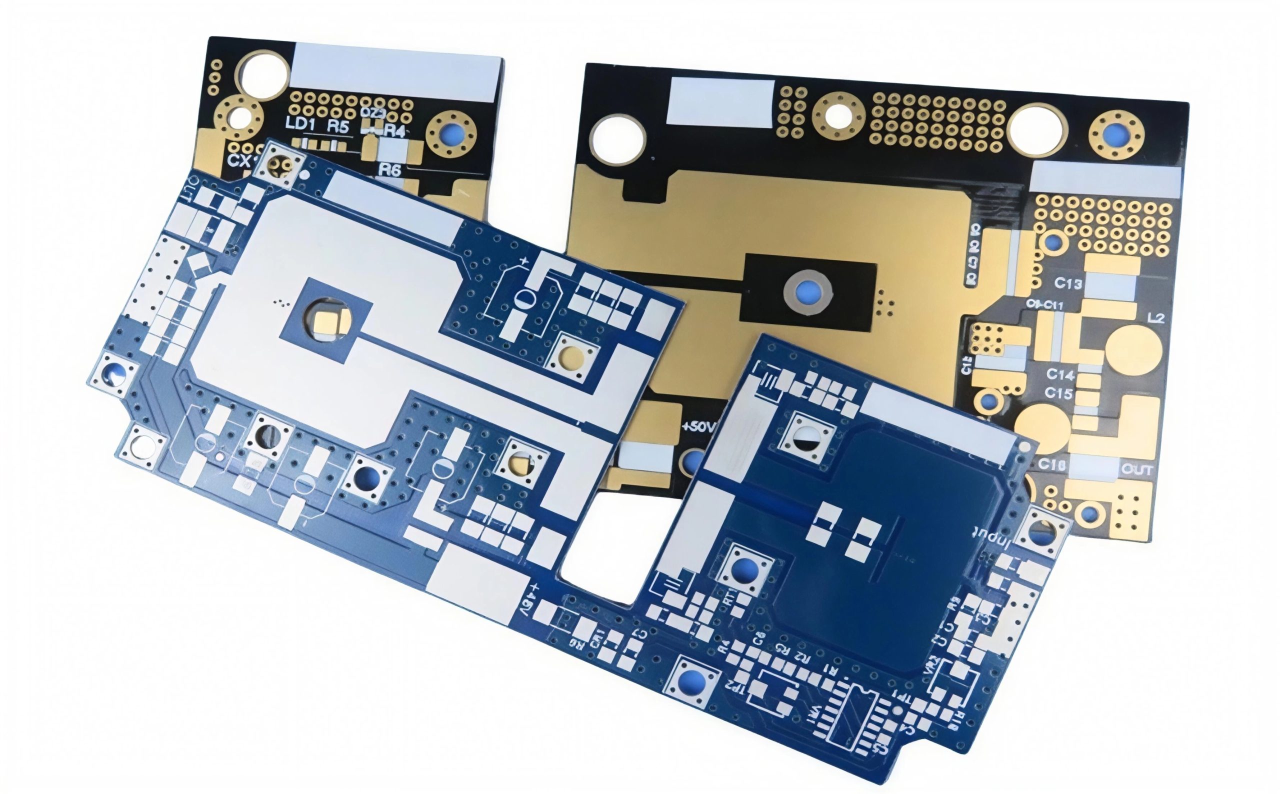
What First-Order HDI Actually Costs
The additional process content is the source of the cost. A first-order construction requires laser drilling for the outer vias, which is slower than mechanical drilling and requires different equipment. It requires the outer layer to be laminated after the core is complete, adding a lamination cycle. It requires tighter registration between the laser-drilled via and the inner layer pad it must reach.
These requirements interact with yield. A laser via that misses its target pad produces an open connection that can only be detected by electrical test, and the detection comes after several process steps have been invested in the panel. The cost of a scrap panel in HDI production is therefore higher than in conventional production, which is why manufacturers price in a yield allowance.
Material choice adds another factor. Because the laser process must stop on the inner layer copper, the dielectric and copper surface treatment have to be compatible with the drilling recipe. A material substitution that appears electrically equivalent may change the laser window, which is one reason material changes on an HDI board require re-qualification rather than a simple notice. Controlling that is part of a disciplined quality system.
When the Trade Is Worth Making
First-order HDI is worth its cost when routing density or via stub behaviour is the binding constraint. Typical triggers include a fine-pitch ball grid array that cannot be escaped with through holes, a layer count that would otherwise become excessive, or a high-speed interface where the stub resonance of a through via is unacceptable.
It is not worth the cost when the design is constrained by something else. If the board has ample routing area, if the interfaces are slow, or if the component pitch is generous, the additional process steps buy nothing. Designers sometimes specify HDI out of habit, inherited from a previous product, and pay for density they never use.
A useful test is to attempt the layout with conventional through holes and identify the exact point at which it fails. If that failure is a genuine routing blockage in a critical area, HDI is justified. If the layout fails because of poor component placement or a suboptimal pin assignment, the solution is elsewhere and costs nothing.
Volume matters in the comparison as well. The process steps that make HDI expensive are largely fixed per panel, so their relative cost falls as boards become larger or as more boards are produced from a panel. A first-order HDI design that looks expensive at prototype quantity may be competitive at volume, and the reverse is also possible if yield does not stabilise.
Design Rules That Change With the Construction
First-order HDI imposes its own layout rules. Blind vias typically have smaller diameters and pads than through vias, which allows tighter routing but reduces the tolerance for registration error. Annular ring requirements differ, and the minimum distance between a via and a trace changes accordingly.
The layer stack also has to be balanced. Because the outer layers are added by lamination, their dielectric thickness is determined by the build-up material rather than by the core construction, and that thickness affects the impedance of outer-layer traces. Designs that assume the same dielectric thickness on all layers will not achieve the impedance targets they calculated.
These rules are most reliably applied when the design layout is developed using the fabricator’s actual capability data rather than a generic design guide. A manufacturer who can supply specific via diameters, annular ring requirements and dielectric thicknesses allows the designer to use the construction efficiently instead of leaving margin for uncertainty.
Qualification and Inspection
Inspection of a first-order HDI board concentrates on the blind vias, because they are the features that conventional inspection methods handle least well. Optical inspection cannot see inside a laser via, and electrical test verifies continuity but not the quality of the plated barrel.
Practical programmes use a combination of methods: cross-section sampling to verify plating and fill, thermal cycling on representative coupons to confirm reliability, and process control on the laser drilling parameters. Each of these addresses a different failure mode, and no single method covers all of them.
The evidence that matters to a customer is production data. A manufacturer who can show via resistance distributions and cross-section results from routine production, rather than from a one-off qualification, is demonstrating that the process holds over time. That is a more meaningful capability statement than a maximum density figure.
Another consideration is design iteration speed. Conventional multilayer boards can be modified and re-fabricated quickly because the process is standard. An HDI board requires the same setup each time, which can lengthen the prototype cycle. Programmes expecting multiple design spins should account for that, and often choose the simpler construction during development and switch later if needed.
Comparing Quotations Fairly
Comparing an HDI quotation with a conventional multilayer quotation requires comparing the same specification. Layer count alone is not sufficient; via construction, minimum line width, impedance tolerance, material grade and inspection requirements all differ substantially between the two, and each affects price.
The productive approach is to ask what the conventional board would need in order to meet the same electrical requirements, and to compare the two complete solutions. Frequently the conventional alternative requires more layers, a better laminate, or a larger outline, and once those are accounted for the gap narrows considerably.
It also helps to ask what the manufacturer would recommend. A fabricator who understands both the design intent and the process cost can often propose a construction between the two extremes, such as a board using buried vias in the core with through holes elsewhere. That option frequently delivers most of the density benefit at a fraction of the HDI premium. Discussing it during manufacturing planning, before the stackup is fixed, is what makes process selection an engineering decision rather than a purchase order detail.
The Practical Conclusion
First-order HDI is a targeted solution to a specific problem, not a generational upgrade over ordinary multilayer boards. It becomes worthwhile when through-hole via density blocks routing or when via stubs degrade a high-speed channel, and it becomes an unnecessary expense when neither condition applies.
Making that judgement well requires understanding the construction rather than the label. Engineers who can describe why a given design needs blind vias, and what would happen without them, are in a position to choose correctly, negotiate meaningfully and avoid paying for density they will never use.
That understanding also improves communication with the manufacturer. A conversation about a specific routing blockage and a specific impedance target produces a better recommendation than a request for an HDI board at a given layer count, and the resulting design is usually both cheaper and easier to produce.