Where to Put a Stiffener on a Flexible Printed Circuit
A stiffener is a patch of rigid material bonded to a flexible circuit to give it local rigidity, and it is what allows a connector, a component or a screw hole to survive on a board that is otherwise designed to bend. Choosing one involves the material, the thickness, the adhesive and the outline, and all four interact with the assembly that will eventually sit on top of them.
Why a Flex Circuit Needs a Stiffener
Flexible material is thin by design, and thin material cannot support a connector that has to be inserted and removed repeatedly or a package that has to be soldered without moving. A stiffener converts a small area of the circuit into something that behaves like a rigid board.
It also controls where the bending happens. By making one region rigid, the designer forces the flexure into the area that was calculated for it, which protects the traces that must not be flexed and keeps the bend radius inside the limit of the copper. Random flexure is what breaks a flexible circuit, so limiting where it can happen is a design decision rather than an assembly detail.
Stiffener Materials Compared
Polyimide is the common choice because it matches the base material, survives the same soldering temperatures and is available in a range of thicknesses. It is an insulator, so it cannot be used where the stiffener must also provide an electrical connection.
Stainless steel and aluminium give much greater stiffness for the same thickness, and both can be bonded to a ground pad to carry heat or to provide a shield. Aluminium is lighter and easier to machine, while stainless steel is stiffer and more resistant to damage during repeated connector insertion. Both conduct heat and electricity, which is an advantage in some designs and a hazard in others.
Thickness, Stiffness and Bend Radius
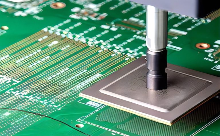
Stiffness rises with the cube of thickness, so a small change in the stiffener or the base material has a large effect on how the finished area behaves. That is why a stiffener is normally specified by thickness and by material rather than by a stiffness figure that nobody can measure on the finished part.
The thickness also has to suit the connector. A connector that has a defined board thickness for its latches will not sit properly on a thinner or thicker sandwich, and the difference is usually discovered when the first assembly is built rather than at the design stage. Checking the connector data against the proposed sandwich before release costs nothing and prevents a tooling change later.
Adhesive Selection and Lamination
The adhesive has to bond at a temperature that the flex circuit can tolerate and then survive the assembly process without creeping. A thermoplastic adhesive flows under heat and pressure, while a thermoset material cures and holds its shape, and the choice changes the lamination cycle. A thermoplastic bond can be reworked with heat, which matters when a stiffener has to be replaced on an expensive circuit.
Adhesive thickness matters as much as the material. A layer that is too thin may not fill the surface texture and leaves voids, while one that is too thick allows the stiffener to move under load. Our bendable circuit materials notes describe the base films that the adhesive bonds to.
Stiffeners Under Connectors and Components
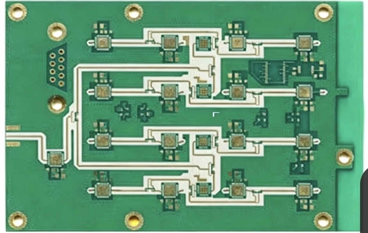
Where a connector is mounted, the stiffener provides the flat surface that the solder joints need and the mechanical strength that the insertion force demands. The outline should extend beyond the connector body so the load is spread into the flex rather than concentrated at the joint.
Under a component the requirement is different. The stiffener prevents the circuit from moving during reflow, which keeps the part from sliding, and it spreads the thermal load so that the adhesive does not soften during soldering. Where a heavy component sits on a flex tail, the stiffener often has to extend under the whole body and a little beyond it. Our multilayer flex processing notes describe how the assembly steps are sequenced.
Thermal and Grounding Stiffeners
A metal stiffener can be part of the electrical design. Bonded to a ground pad with a conductive adhesive, it provides a low impedance connection, a heat spreader and a shield in one item, which is often cheaper than solving the three problems separately.
The connection has to be defined explicitly, because a metal stiffener that touches a pad without an intentional bond creates an unreliable contact that changes with temperature and humidity. Conductive adhesive, or a defined solder or rivet joint, is what makes the connection repeatable.
Design Rules for Outline and Tolerance
The stiffener outline needs a tolerance of its own, and it should not be assumed that it will land exactly where the drawing shows it. Adhesive flow during lamination moves the material slightly, and the finished outline is usually routed or punched after bonding.
Clearance to the bend area matters most. A stiffener that ends too close to a bend line raises the local stiffness and forces the flexure into a smaller radius, which is a reliable way of cracking the copper. Our board outline notes cover the general tolerance practice.
Assembly and Handling Implications
A stiffened area changes the way the circuit behaves in an assembly machine. The pick and place head sees a local step in thickness, the stencil cannot print across the transition, and the panel may need a carrier to keep it flat through the printer. Planning that carrier early avoids a surprise when the first production batch reaches the line.
Rework is harder as well, since heat has to pass through the stiffener to reach the joint on some designs. That is one reason the stiffener outline should be shown on the assembly drawing rather than only on the fabrication drawing that the assembly team never sees.
Specifying a Stiffener on the Drawing
The drawing should name the material, the thickness, the adhesive type, the outline tolerance and the surface finish, and it should say whether the stiffener is to be plated or left bare. Where a metal stiffener carries a ground connection, the bonding method has to be stated as well.
Showing the stiffener on the assembly drawing prevents the most common error, which is a connector specified for a thickness that the bonding process never produces. Our fabrication notes checklist lists the items worth confirming before the first panel is built.
FAQ
Can a stiffener be added after assembly? It can, but bonding after soldering means the adhesive never sees the reflow temperature, which changes the cure and the mechanical result. Building the stiffener into the circuit is normally the more reliable route.
How thick should a stiffener be? Thick enough to give the connector or component the support it needs, and no thicker. Common practice is to match the target total thickness specified by the connector manufacturer and to work back from there.
How does gopcb build flex circuits with stiffeners? We confirm the material, thickness and adhesive against the assembly requirement, laminate and cure to a recorded cycle, route the outline to the agreed tolerance, and supply the parts on a carrier where the assembly process needs one.