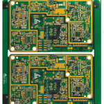
As electronic products continue to become smaller, lighter, and more integrated, flexible printed circuits are increasingly used to connect electronic modules and components in applications where conventional rigid PCBs cannot provide the required flexibility.
Although the basic principles of Flexible PCB Assembly are similar to those used for rigid PCB assembly, the manufacturing process requires additional considerations because flexible circuits are thin, lightweight, and mechanically less rigid.
During FPC Assembly, manufacturers may use different processes depending on the FPC structure, component type, assembly method, production volume, and product requirements. Compared with conventional rigid-board assembly, flexible PCB assembly places greater emphasis on mechanical support, positioning accuracy, flatness, cleanliness, and handling.
1. What Is Flexible PCB Assembly?
Flexible PCB Assembly refers to the process of mounting electronic components onto a flexible printed circuit and completing the required soldering, inspection, and testing processes.
A typical assembly may include:
- Solder paste printing
- Component placement
- Reflow soldering
- Through-hole soldering where required
- Connector installation
- AOI inspection
- X-ray inspection for applicable components
- Electrical testing
- Functional testing
- Final inspection
The exact process depends on whether the FPC contains SMT components, through-hole components, connectors, or a combination of different technologies.
Because an FPC can deform easily, it generally requires additional support during assembly.
2. Why Does FPC Assembly Require Additional Support?
A flexible circuit is designed to bend, which is one of its primary advantages. However, this same flexibility can create difficulties during automated assembly.
For example, a thin FPC may not remain sufficiently flat during solder paste printing or component placement. Excessive movement can affect stencil alignment, solder paste deposition, component placement accuracy, and solder-joint quality.
For this reason, an FPC may be temporarily or permanently supported by:
- Rigid carrier boards
- Tooling fixtures
- Vacuum fixtures
- FR-4 stiffeners
- Stainless-steel stiffeners
- Other application-specific support structures
The support method should be selected according to the FPC thickness, component distribution, assembly process, and mechanical requirements.
3. FPC Assembly on a Rigid Carrier
One common approach is to attach the flexible circuit to a rigid carrier during SMT Assembly.
The carrier provides mechanical support and helps keep the FPC flat during printing and component placement. It can also improve positioning repeatability when the flexible circuit is too thin to be handled reliably by standard SMT equipment on its own.
Important factors include:
Flatness
The FPC must remain sufficiently flat in the printing area. Local lifting or deformation can affect solder paste deposition.
Positioning Accuracy
The FPC and carrier must maintain a stable relative position so that component pads align correctly with the stencil and placement coordinates.
Repeatability
For mass production, the loading and unloading method should provide consistent positioning from panel to panel.
Carrier Design
The carrier should provide sufficient support without obstructing component placement, soldering, inspection, or thermal exposure.
Proper fixture design is therefore an important part of reliable FPC Manufacturing.
4. Typical Characteristics of Flexible PCB Assembly
Compared with rigid PCB assembly, FPC assembly has several distinctive characteristics.
Lightweight and Flexible Construction
FPCs are thinner and more flexible than conventional rigid boards. This provides major advantages for compact products but also creates additional handling and assembly challenges.
Relatively Limited Component Density in Some Applications
Many FPCs are primarily used as interconnection circuits between functional modules rather than as complete electronic control boards.
As a result, some FPC assemblies contain relatively few components and may primarily consist of connectors and a limited number of passive or active devices.
However, this is not a universal characteristic. Advanced FPCs can support dense SMT layouts, fine-pitch components, and highly integrated electronic functions.
Panelization for Assembly Efficiency
For small FPCs, individual-unit assembly can reduce production efficiency.
Manufacturers may therefore use panelization or carrier-based arrays to assemble multiple FPC units in a single production cycle.
Depending on the material and board design, the individual circuits can later be separated using appropriate routing, punching, laser cutting, scoring, or other controlled methods.
V-scoring should not be considered universally suitable for flexible circuits because the appropriate depanelization method depends on the FPC structure and material stackup.
5. High Quality Requirements for FPC Assembly
Quality requirements for FPC Assembly can be particularly demanding because the finished circuit may operate under repeated bending, vibration, thermal cycling, or mechanical movement.
Important quality-control requirements include:
- Accurate component placement
- Reliable solder joints
- Clean FPC surfaces
- Correct solder paste deposition
- Controlled reflow profiles
- Stable connector interfaces
- Appropriate mechanical support
- Reliable adhesion of stiffeners
- Proper handling of flexible areas
- Electrical continuity and isolation
- Long-term mechanical reliability
For applications involving dynamic flexing, solder joints and component interfaces may experience mechanical stress. The FPC design must therefore distinguish between static bending and dynamic bending requirements.
6. Cleanliness and Contamination Control
Cleanliness is an important consideration in FPC Assembly.
Contamination such as flux residues, dust, oils, or foreign particles can affect soldering performance, electrical insulation, connector reliability, and long-term product performance.
Depending on the application, manufacturers may establish specific cleaning and cleanliness requirements.
For high-reliability products, cleanliness should be controlled throughout the manufacturing process rather than relying only on final cleaning.
7. ESD Protection During FPC Assembly
Flexible circuits can be used with sensitive electronic components, making electrostatic discharge protection an important consideration.
During assembly, appropriate ESD controls may include:
- ESD-safe workstations
- Grounded personnel
- Conductive or dissipative work surfaces
- Proper component storage
- ESD-safe packaging
- Controlled handling procedures
ESD protection is particularly important when the FPC assembly contains sensitive semiconductor devices.
8. SMT Assembly for Flexible PCBs
SMT Assembly is widely used when components need to be mounted directly onto a flexible circuit.
A typical SMT process includes:
- FPC loading and alignment
- Stencil printing
- Solder paste inspection
- Component placement
- Reflow soldering
- Automated optical inspection
- X-ray inspection when required
- Electrical or functional testing
Because the FPC can deform during printing, reliable support is essential.
The stencil, carrier, printing parameters, component placement program, and reflow profile should be developed as an integrated process.
9. Reflow Soldering Considerations
Reflow soldering is a critical step in FPC Assembly.
The reflow profile should be established according to the solder paste alloy, component specifications, FPC materials, copper distribution, and thermal characteristics of the assembly.
Important parameters include:
- Heating rate
- Preheat conditions
- Soak conditions where applicable
- Peak temperature
- Time above liquidus
- Cooling rate
There is no single reflow profile suitable for every FPC assembly.
Excessive thermal exposure may affect the flexible substrate, adhesive systems, stiffeners, or other materials. Insufficient heating, on the other hand, can result in poor solder wetting or incomplete solder-joint formation.
Therefore, profile verification is an important part of production qualification.
10. FPC Stiffeners and Assembly Reliability
Many FPCs use localized stiffeners to improve assembly performance.
A stiffener can increase the local thickness and rigidity of an FPC, particularly around connector interfaces and component mounting areas.
Common stiffener materials include:
- FR-4
- Polyimide
- Stainless steel
- Aluminum
The selection depends on the mechanical and thermal requirements of the application.
For connector areas, a stiffener can help maintain dimensional stability during insertion and removal. For SMT areas, it can also provide additional mechanical support during assembly.
However, stiffeners should be positioned carefully so that they do not unnecessarily restrict the required bending region.
11. FPC Assembly Cost Factors
The cost of Flexible PCB Assembly can be higher than conventional rigid PCB assembly in certain applications.
Several factors can contribute to the total cost:
Specialized Fixtures
Flexible circuits often require carriers, fixtures, or customized tooling to maintain flatness and positioning accuracy.
Lower Throughput in Some Applications
If the FPC requires manual loading, additional alignment, or special handling, production throughput may be lower than that of a conventional rigid PCB.
Specialized Handling
Operators and equipment may require additional procedures to prevent bending, scratching, contamination, or mechanical damage.
Higher Process-Control Requirements
High-reliability FPC applications may require tighter controls for cleanliness, soldering, inspection, and mechanical handling.
Material and Stiffener Costs
Flexible substrates and specialized reinforcement materials can also influence total manufacturing cost.
However, the actual cost depends on the FPC structure, component count, production volume, assembly technology, testing requirements, and fixture design.
12. FPC Assembly Quality Control
A robust FPC Manufacturing process should include quality control throughout the complete production flow.
Key inspection stages may include:
Incoming Material Inspection
The manufacturer verifies FPC dimensions, surface condition, material specifications, stiffeners, and other incoming materials.
Solder Paste Inspection
SPI can evaluate solder paste volume, position, and coverage after stencil printing.
Automated Optical Inspection
AOI can identify many visible soldering and component-placement defects, including missing components, polarity errors, insufficient solder, and solder bridges.
X-Ray Inspection
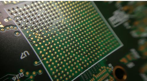
For hidden solder joints, such as certain BGA or bottom-terminated components, X-ray inspection may be required because these joints cannot be fully evaluated by conventional optical inspection.
Electrical Testing
Electrical testing can verify continuity and isolation according to the requirements of the circuit.
Functional Testing
Where required, functional testing can verify whether the assembled FPC performs its intended electrical function.
13. FPC Assembly Reliability Considerations
The reliability of an FPC assembly depends on more than solder-joint quality.
Engineers should consider the interaction between:
- Flexible substrate
- Copper traces
- Solder joints
- Components
- Stiffeners
- Adhesives
- Connectors
- Mechanical fixtures
- Bending conditions
- Thermal cycling
For static-flex applications, the primary concern may be assembly and installation.
For dynamic-flex applications, repeated bending introduces additional mechanical fatigue. Trace routing, copper type, bend radius, component placement, stiffener boundaries, and neutral-axis considerations may become important.
Therefore, FPC reliability should be evaluated according to the actual mechanical environment rather than using a single generic bending specification.
14. Flexible PCB Assembly Applications
Flexible Circuit technology is widely used in applications where compactness, weight reduction, or three-dimensional interconnection is important.
Typical applications include:
- Smartphones
- Digital cameras
- Wearable devices
- Automotive electronics
- Medical electronics
- Industrial equipment
- Displays
- Sensors
- Consumer electronics
- Battery and power-management systems
FPCs can replace traditional wire harnesses or rigid interconnection structures in applications where space is limited or movement is required.
15. Kingda’s Flexible PCB Assembly Support
At Kingda, flexible circuit manufacturing and assembly are treated as an integrated engineering process.
From FPC material selection and circuit design to stiffener application, fixture development, SMT Assembly, soldering, inspection, and testing, each stage can affect final product reliability.
Kingda can help customers evaluate FPC assembly requirements at the design stage, including:
- Component placement
- Connector locations
- Stiffener requirements
- Bending areas
- Carrier and fixture requirements
- SMT process compatibility
- Inspection requirements
- Reliability considerations
Early DFM evaluation can help reduce assembly risks and minimize unnecessary prototype iterations.
Conclusion
Flexible PCB Assembly provides an effective solution for compact, lightweight, and space-constrained electronic products. However, the flexibility that makes an FPC valuable also creates unique assembly challenges.
Unlike conventional rigid PCB assembly, FPC assembly often requires additional mechanical support, specialized fixtures, controlled handling, and careful process optimization.
Reliable FPC Assembly depends on coordinated control of printing, placement, reflow soldering, inspection, stiffener design, cleanliness, and mechanical reliability.
As electronic products continue to become smaller and more integrated, Flexible PCB technology will play an increasingly important role in modern electronic interconnection. Working with an experienced FPC Manufacturing partner such as Kingda can help ensure that the flexible circuit is designed and assembled for both manufacturability and long-term reliability.