FPC-to-PCB Connections: 7 Common Methods Explained
How Does FPC Connect to PCB?
As electronic products become smaller, thinner, and more integrated, FPC to PCB connection technology has become increasingly important. A Flexible Printed Circuit (FPC) provides lightweight construction, flexibility, and three-dimensional routing, while a rigid PCB provides mechanical support, component mounting, and stable electrical performance.
The two boards can be electrically interconnected in several ways. The best method depends on factors such as available space, connection frequency, vibration, production volume, electrical requirements, serviceability, and cost.
For projects requiring integrated flexible circuits, Flexible PCB Assembly can eliminate unnecessary cables and connectors while providing a compact interconnection solution.
This guide explains seven practical FPC PCB connection methods, their operating principles, advantages, limitations, and typical applications.
1. FPC Connector Connection
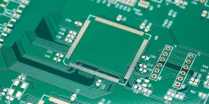
An FPC connector is one of the most widely used solutions for connecting an FPC to a rigid PCB. It provides a detachable electrical interface and is particularly useful when the flexible cable must be installed, removed, or replaced during assembly or servicing.
Board-to-Board and Board-to-FPC Connectors
Connector-based connections generally rely on metal terminals that make contact with conductive pads on the FPC or PCB. The connector itself is normally soldered to the PCB, while the FPC is inserted into the connector.
Common connector structures include:
- Board-to-board connectors
- Board-to-FPC connectors
- Male/female connectors
- Locking FPC connectors
- Top-contact and bottom-contact connectors
- Single-sided and double-sided contact connectors
The major advantage is easy assembly and disassembly. Connectors can also support compact pitches, making them suitable for smartphones, wearable electronics, displays, cameras, battery modules, and other space-constrained products.
However, connectors add component cost and occupy board space. Contact resistance, insertion force, connector retention, and vibration resistance must also be considered during design.
For projects that require both flexible and rigid circuit technologies, PCB Manufacturing can provide rigid, flexible, and rigid-flex PCB options under one manufacturing workflow.
FPC Insertion Connectors
An FPC insertion connector, often called an FPC socket, is specifically designed for inserting a flexible circuit directly into a connector mounted on the PCB.
The connector generally consists of a housing, contacts, actuator or locking mechanism, and solder terminals. The FPC normally uses exposed contact pads or gold fingers, with a stiffener added behind the contact area when additional mechanical support is required.
The main benefits include:
- Repeated insertion and removal
- Simple maintenance
- No direct soldering of the FPC required
- High wiring density
- Compact overall structure
Locking mechanisms are especially useful where vibration or shock could otherwise cause intermittent contact.
2. Terminal Connection
Terminal connection is another mechanical method for establishing an electrical connection between an FPC and PCB.
In this approach, a dedicated terminal or contact component mechanically penetrates or clamps the conductive pad area of the FPC. The terminal is normally attached to the corresponding PCB structure to create a reliable electrical path.
This method is generally more appropriate for industrial equipment, control panels, and applications where relatively large connection pitches are acceptable.
Compared with fine-pitch FPC connectors, terminal connections usually require more space and are therefore less suitable for highly miniaturized consumer electronics.
When the product requires a complete manufacturing solution rather than a standalone FPC, PCB Assembly can integrate flexible, rigid, and rigid-flex boards with SMT, through-hole, inspection, and testing processes.
3. Half-Hole Gold Finger Connection
A half-hole gold finger connection uses exposed contact pads on the FPC together with plated half-holes along the edge of the connection area.
During soldering, the plated half-holes allow solder to flow around the edge of the FPC contact area, creating a stronger mechanical and electrical connection to the PCB.
Advantages
- No separate connector required
- Low additional component cost
- Very low overall connection height
- Suitable for compact mechanical structures
- Direct solder connection between FPC and PCB
Limitations
The manufacturing and soldering process requires careful control. Edge formation, pad registration, solder bridging, and short circuits can become concerns, particularly with fine-pitch designs.
This method is therefore useful for prototypes, compact products, and applications where connector height must be minimized.
4. Reinforcement and Plated Connection
In some designs, an FR-4 rigid section is combined with an FPC through reinforcement and lamination processes. The rigid section provides mechanical support, while plated holes or other conductive structures provide the electrical path between the two sections.
This approach can be considered when a full rigid-flex construction is unnecessary but the product still requires some of the mechanical advantages of a rigid section.
Key Advantages
- Combines flexible and rigid circuit functions
- Can reduce the need for separate mechanical structures
- May cost less than a complex rigid-flex design
- Suitable for relatively simple interconnection requirements
However, the design is generally less suitable for high-density or highly complex circuits. Electrical and mechanical requirements should be evaluated during the engineering stage.
5. Rigid-Flex PCB
A Rigid-Flex PCB integrates rigid PCB sections and flexible circuit sections into a single interconnected board structure.
Instead of manufacturing a separate FPC and rigid PCB and connecting them with an additional connector or cable, the flexible section becomes part of the PCB itself.
How Rigid-Flex PCB Works
A rigid-flex structure typically combines rigid materials such as FR-4 with flexible polyimide-based circuit sections. The different sections are integrated through controlled lamination and manufacturing processes.
This approach provides:
- Fewer connectors
- Fewer cables and wiring points
- Better three-dimensional integration
- Reduced assembly complexity
- Improved resistance to vibration when properly designed
- High-density routing capabilities
Rigid-flex PCB technology is particularly valuable for aerospace, automotive electronics, medical devices, cameras, wearable electronics, industrial equipment, and compact consumer products.
According to GOPCBA’s manufacturing information, rigid-flex boards can integrate multiple circuit regions while reducing connectors, cables, and wiring, helping improve mechanical integration and reliability.
When Should You Choose Rigid-Flex PCB?
Rigid-flex is usually worth considering when:
- Internal space is highly constrained
- The product requires three-dimensional routing
- Multiple connectors can be eliminated
- Vibration resistance is important
- High-density interconnection is required
- Long-term mechanical reliability is more important than minimum initial cost
The main disadvantage is higher manufacturing complexity and cost compared with conventional rigid or flexible PCBs.
6. Conductive Adhesive Connection
Conductive adhesive provides another method for creating an electrical connection between an FPC and PCB.
The adhesive contains conductive particles that establish electrical conductivity when the FPC and PCB are pressed together under controlled conditions.
Advantages
- Low-temperature or no conventional soldering process
- Suitable for heat-sensitive components
- Relatively simple assembly
- Useful for compact electronic products
- Can support rapid prototyping
Limitations
Conductive adhesive generally requires careful control of bonding pressure, curing conditions, contact area, and environmental reliability.
Its electrical and long-term mechanical performance may also differ from conventional soldered or connector-based connections. Therefore, it should be selected according to the application’s temperature, humidity, vibration, and lifetime requirements.
For prototype and low-volume projects, Rapid PCB Prototyping can help engineers validate flexible and rigid-flex designs before moving into larger-scale production.
7. Direct Solder Connection
Direct soldering can also be used to electrically connect an FPC to a PCB when the FPC has an appropriately designed contact area.
In this configuration, conductive pads on the FPC are aligned with corresponding PCB pads and joined using solder. Depending on the design, the process can be performed manually, with hot-bar or thermode equipment, or through an appropriate automated soldering process.
Advantages
- Simple electrical structure
- No separate connector required
- Low component count
- Low profile
- Suitable for compact products
Challenges
The flexible substrate is more sensitive to thermal and mechanical stress than a conventional rigid PCB. Therefore, soldering temperature, heating time, pad design, reinforcement, alignment, and strain relief must be carefully controlled.
A stiffener is often added to the FPC connection area to improve dimensional stability and prevent mechanical damage during assembly.
Comparison of 7 FPC-to-PCB Connection Methods
| Connection Method | Main Advantages | Main Limitations | Typical Applications |
|---|---|---|---|
| FPC Connector | Detachable, easy maintenance, high density | Higher cost and space requirement | Smartphones, displays, wearables, cameras |
| Terminal Connection | Strong mechanical retention | Requires more space | Industrial controls, equipment panels |
| Half-Hole Gold Finger | Low profile, no connector | Fine-pitch soldering can be difficult | Compact products, prototypes |
| Reinforcement & Plated Connection | Combines rigid and flexible functions | Limited for complex high-density designs | Simple hybrid structures |
| Rigid-Flex PCB | Integrated structure, fewer connectors, high reliability | Higher manufacturing cost | Automotive, aerospace, medical, cameras |
| Conductive Adhesive | Low-temperature process, simple assembly | Long-term reliability requires evaluation | Wearables, compact electronics |
| Direct Solder Connection | Low profile, few components | Thermal and mechanical stress | Compact electronic modules |
How to Choose the Right FPC-to-PCB Connection
There is no single connection method that is ideal for every application. The correct choice should be based on electrical, mechanical, manufacturing, and service requirements.
1. Consider Available Space
For extremely thin products, low-profile soldering or half-hole connections may be preferable. Where additional vertical space is available, an FPC connector can provide easier assembly and maintenance.
2. Consider Whether the Connection Must Be Detachable
If the FPC needs to be replaced during product maintenance, an FPC connector is usually more practical than a permanent soldered connection.
For permanent interconnections, rigid-flex PCB or direct soldering may provide a cleaner structure.
3. Consider Vibration and Mechanical Stress
Automotive, industrial, aerospace, and other demanding applications may experience vibration, shock, and thermal cycling.
A properly designed rigid-flex structure can reduce the number of separate connection points. For connector-based solutions, locking mechanisms and appropriate mechanical retention should be considered.
4. Consider Production Volume
For high-volume products, connector-based designs can be optimized for automated assembly. For prototypes and low-volume production, simpler direct connections may sometimes reduce tooling and component costs.
GOPCBA supports prototype, low-volume, and mass-production PCB assembly, including flexible and rigid-flex PCB assemblies.
5. Consider Signal Integrity
High-speed or sensitive signals require careful control of impedance, return paths, connector characteristics, trace geometry, and layer structure.
For high-speed applications, the FPC-to-PCB transition should be treated as part of the complete signal path rather than as an isolated mechanical connection.
FPC vs. Rigid-Flex PCB: Which Is Better?
A separate FPC connected to a rigid PCB can provide flexibility and easier module replacement. However, every additional connector or cable creates another electrical and mechanical interface.
A rigid-flex PCB integrates the flexible interconnection directly into the board structure. This can reduce connector count and simplify three-dimensional product assembly.
GOPCBA supports single-sided, double-sided, multilayer, and HDI flexible PCBs as well as single-sided, double-sided, multilayer, and HDI rigid-flex PCB structures.
The choice therefore depends on the product’s priorities:
- Need easy replacement: FPC connector
- Need minimum height: Direct solder or half-hole connection
- Need strong mechanical integration: Rigid-flex PCB
- Need rapid prototyping: Simple connector or solder connection
- Need high-density routing: Fine-pitch connector or rigid-flex PCB
- Need lower component count: Direct solder or rigid-flex PCB
- Need long-term reliability: Properly engineered rigid-flex or mechanically secured connection
Manufacturing Considerations for FPC and PCB Connections
Successful FPC interconnection depends not only on the connection method but also on PCB fabrication and assembly quality.
Important design considerations include:
- FPC thickness and copper thickness
- Pad geometry and pitch
- Surface finish
- FPC stiffener design
- Bend radius
- Connector specifications
- Soldering temperature
- Mechanical strain relief
- Alignment tolerance
- Vibration and thermal cycling
- Electrical testing
- DFM and DFA requirements
For complex products, early engineering review can identify manufacturability problems before fabrication. GOPCBA provides DFM and DFA support, BOM verification, Gerber review, component analysis, and production optimization.
Conclusion
FPC and PCB can be electrically interconnected through several technologies, including FPC to PCB connection using connectors, terminals, half-hole gold fingers, reinforcement structures, rigid-flex PCB, conductive adhesive, and direct soldering.
The most suitable solution depends on the product’s available space, required flexibility, connection frequency, mechanical environment, production volume, signal requirements, and cost target.
For simple detachable connections, an FPC connector is often the most practical choice. For permanent and highly integrated products, rigid-flex PCB technology can eliminate connectors and cables while improving three-dimensional integration. For compact prototypes, direct soldering or low-profile connection methods may provide a simpler solution.
GOPCBA provides PCB fabrication and assembly services covering rigid PCB, Flexible PCB, and Rigid-Flex PCB, together with SMT, through-hole assembly, testing, and engineering support.
For a custom FPC, PCB, or rigid-flex project, Contact GOPCBA to discuss your board structure, assembly requirements, and manufacturing requirements.