High-Speed PCB Materials: Properties, Selection Guide & PCB Design and Manufacturing
In today’s rapidly evolving electronics industry, printed circuit boards (PCBs) are the foundation of almost every electronic device and system. They support applications ranging from low-power consumer electronics to high-power computing, telecommunications, aerospace, automotive, and defense systems.
However, not all PCBs are designed to handle high-speed signals. High-Speed PCB technology differs from conventional PCB technology in terms of material selection, stackup architecture, trace geometry, impedance control, and signal-integrity requirements.
High-speed circuit boards are carefully engineered to transmit signals with minimal loss, distortion, crosstalk, and reflection. As signal frequencies and data rates continue to increase, choosing the appropriate PCB material becomes increasingly important.
Before starting a high-speed PCB Design, engineers should understand the electrical, thermal, mechanical, and chemical characteristics of available PCB materials. Selecting the right material at the beginning of the design process can significantly affect signal integrity, reliability, manufacturability, and overall product cost.
What Is a High-Speed PCB?
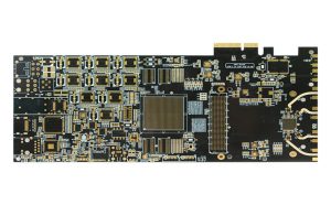
A High-Speed PCB is a printed circuit board designed to support high-frequency signals or fast signal transitions while maintaining acceptable signal integrity and power integrity.
The term “high speed” does not depend solely on the clock frequency. A digital signal with a relatively low repetition rate can still have very fast rise and fall times, making transmission-line effects important.
As signal edges become faster, PCB traces can no longer always be treated as simple electrical connections. Trace impedance, propagation delay, dielectric properties, return-current paths, crosstalk, via transitions, and transmission losses must all be considered.
High-speed PCBs are commonly used in:
- High-performance computing systems
- Networking and telecommunications equipment
- Data-center hardware
- Automotive electronics
- Radar and wireless communication systems
- Aerospace and defense electronics
- Medical electronics
- Industrial control equipment
- High-speed storage and interface systems
For these applications, material selection is an important part of controlling signal loss, impedance variation, thermal performance, and long-term reliability.
Key Properties of High-Speed PCB Materials
Many PCB materials are available for high-speed applications, including conventional FR-4 systems, low-loss FR-4 variants, PTFE-based laminates, hydrocarbon/ceramic materials, and other high-frequency laminate systems.
Each material has different electrical, thermal, mechanical, and chemical properties.
When selecting a material for PCB Manufacturing, engineers should evaluate the complete set of requirements rather than focusing on a single specification.
Thermal Properties
Thermal performance is particularly important for high-speed PCBs used in high-power or high-density electronic systems.
Glass Transition Temperature (Tg)
The glass transition temperature, or Tg, is the temperature at which a polymer-based PCB material transitions from a relatively rigid glassy state toward a softer, more rubber-like state.
A higher Tg generally provides greater thermal margin for applications exposed to elevated temperatures. However, Tg should not be considered in isolation because other parameters, such as Td and CTE, also affect PCB reliability.
Decomposition Temperature (Td)
The decomposition temperature, or Td, indicates the temperature at which a PCB material begins to undergo significant thermal decomposition.
Td is particularly important during lead-free assembly and other high-temperature manufacturing processes.
A suitable PCB laminate should provide sufficient thermal stability for the expected fabrication, assembly, and operating conditions.
Coefficient of Thermal Expansion (CTE)
The coefficient of thermal expansion, or CTE, describes how much a material expands or contracts as temperature changes.
PCB laminates and copper have different CTE values. Because copper and dielectric materials expand at different rates, excessive thermal cycling can place mechanical stress on plated through-holes, vias, and interconnections.
For multilayer and HDI structures, controlling CTE in the appropriate directions is important for long-term reliability.
Thermal Conductivity
Thermal conductivity, commonly represented by k, describes how effectively a material conducts heat.
A higher thermal conductivity can be beneficial for dissipating heat from high-power components. However, high thermal conductivity is not automatically the most important requirement for every high-speed PCB.
For signal-integrity-driven designs, engineers must also consider Dk, Df, copper roughness, moisture absorption, CTE, and other material properties.
Electrical Properties
Electrical characteristics are among the most important factors in high-speed PCB material selection.
Dielectric Constant (Dk)
The dielectric constant, or Dk, describes the relative permittivity of a dielectric material.
Dk affects signal propagation velocity and is therefore directly related to transmission-line behavior and controlled impedance.
For a given PCB geometry, changes in Dk can affect:
- Characteristic impedance
- Signal propagation delay
- Trace dimensions
- Phase behavior
- Differential-pair performance
Importantly, the Dk value reported on a laminate datasheet may be measured using a specific test method and at a particular frequency. It should not automatically be treated as the exact effective Dk of a finished PCB transmission line.
For accurate high-speed PCB Design, engineers should use material data that is appropriate for the operating frequency and design methodology.
Dissipation Factor (Df)
The dissipation factor, or Df, represents dielectric loss within the PCB material.
A lower Df generally indicates lower dielectric loss, which is beneficial for high-speed and high-frequency signal transmission.
As frequency and transmission distance increase, dielectric loss can become a significant contributor to overall insertion loss.
Therefore, low-loss and ultra-low-loss laminate systems are often considered for demanding high-speed applications.
Volume Resistivity
Volume resistivity describes the electrical resistance of a material to current flowing through its volume.
High-quality PCB dielectric materials generally require strong insulation performance and stable electrical characteristics under the expected temperature and humidity conditions.
Volume resistivity is particularly important when long-term insulation reliability is required.
Mechanical Properties
Electrical performance is only one part of high-speed PCB reliability. Mechanical properties must also be considered.
Flexural Strength
Flexural strength describes a material’s ability to withstand bending-related mechanical stress before failure.
This characteristic can be important in applications exposed to vibration, mechanical shock, repeated thermal cycling, or structural stress.
Delamination Resistance
Multilayer PCBs contain multiple copper and dielectric layers bonded together through lamination.
Poor material compatibility or excessive thermal stress can increase the risk of delamination.
Material systems should therefore be evaluated for thermal resistance, interlayer adhesion, moisture behavior, and compatibility with the intended PCB Manufacturing process.
Density
PCB material density affects overall board weight and can become important in applications such as aerospace, portable electronics, and other weight-sensitive systems.
However, density should be evaluated together with electrical, thermal, mechanical, and manufacturing requirements.
Chemical Properties
Chemical characteristics can also influence the long-term reliability of high-speed PCB materials.
Moisture Absorption
Moisture absorption is an important consideration because water can affect dielectric behavior.
Moisture can change the effective dielectric properties of a PCB material and may also influence insulation reliability and high-frequency signal performance.
For demanding high-speed applications, materials with low moisture absorption are often preferred.
The actual moisture absorption value should always be obtained from the manufacturer’s datasheet rather than assuming a single value for an entire material family.
Flammability Rating
PCB laminates used in many electronic products are evaluated according to recognized flammability standards such as UL 94.
For example, UL 94 classifications characterize the flammability behavior of plastic materials under defined test conditions.
The required rating depends on the product, safety requirements, applicable regulations, and end application.
Important Considerations When Selecting High-Speed PCB Materials
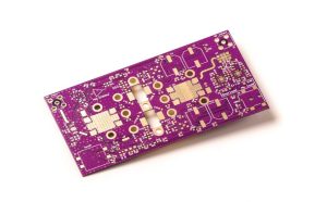
Choosing a material for a High-Speed PCB requires more than simply selecting the laminate with the lowest Df.
Engineers should evaluate the interaction between electrical performance, thermal behavior, mechanical reliability, manufacturing capability, and cost.
Dk Consistency and Stability
Stable dielectric properties are essential for controlled-impedance designs.
Changes in Dk can affect impedance and propagation delay. Engineers should therefore consider Dk stability over the relevant frequency, temperature, and environmental conditions.
For multilayer boards, the dielectric properties of different materials should also be carefully considered when building a hybrid stackup.
CTE Compatibility
Different materials in a PCB stackup have different coefficients of thermal expansion.
If the materials are poorly matched, repeated heating and cooling can increase mechanical stress on copper structures and plated interconnections.
This is particularly important for multilayer boards, HDI structures, large PCBs, and products that experience significant thermal cycling.
Should You Avoid FR-4?
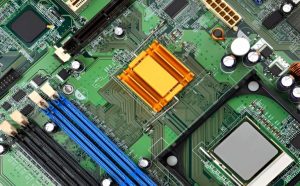
FR-4 should not automatically be excluded from every high-speed PCB design.
Standard FR-4 materials are widely used because they offer a good balance of electrical performance, mechanical strength, availability, manufacturability, and cost.
However, as data rates, frequencies, and transmission distances increase, conventional FR-4 may not provide sufficiently low dielectric loss or stable electrical performance for certain applications.
In these situations, engineers may consider low-loss FR-4 or specialized high-frequency laminates.
The appropriate material should be selected according to the actual signal-integrity requirements rather than simply classifying a PCB as “high speed.”
Control Copper Roughness
Copper surface roughness can influence high-frequency conductor loss.
At higher frequencies, current tends to concentrate near the conductor surface because of the skin effect. Surface roughness can increase the effective path length and contribute to additional insertion loss.
Therefore, copper foil type and surface roughness should be considered when designing high-speed transmission lines.
Avoid Conductive Anodic Filament (CAF) Risk
Conductive anodic filament, or CAF, is an electrochemical failure mechanism that can develop under certain combinations of moisture, electric field, contamination, material structure, and manufacturing conditions.
CAF can create unintended conductive paths between features such as vias.
For applications requiring high insulation reliability, engineers should select appropriate materials and work with the PCB manufacturer to control design spacing, material selection, processing, and environmental conditions.
Mechanical Stress
High-speed PCBs used in demanding environments may experience vibration, shock, thermal cycling, mechanical loading, and other stresses.
The selected material must therefore provide adequate mechanical reliability for the intended application.
Aerospace, automotive, industrial, and defense electronics may require more extensive mechanical and environmental qualification than ordinary consumer electronics.
Tight Impedance Control
Controlled impedance is essential for many high-speed interfaces.
If the actual impedance differs significantly from the target impedance, signal reflections can increase and signal quality may deteriorate.
Impedance depends on several variables, including:
- Trace width
- Trace thickness
- Dielectric thickness
- Dk
- Copper roughness
- Reference-plane geometry
- Manufacturing tolerances
Therefore, impedance should be treated as a complete PCB stackup and manufacturing-control problem rather than a material-only parameter.
Cost
Specialized high-speed laminates can cost considerably more than standard FR-4.
However, the lowest material price does not necessarily produce the lowest overall product cost.
Engineers should consider:
- Material cost
- Fabrication cost
- Manufacturing yield
- Assembly requirements
- Testing cost
- Prototype cost
- Reliability requirements
- Expected production volume
For cost-sensitive projects, designers can work with the PCB manufacturer to identify a material that meets the electrical requirements without introducing unnecessary material costs.
Manufacturing Capability
Material selection should be coordinated with the PCB manufacturer at an early stage.
Specialized laminates can introduce different requirements for:
- Lamination
- Drilling
- Routing
- Etching
- Copper plating
- Surface treatment
- Impedance control
- Thermal processing
- Assembly
Early communication helps ensure that the selected material is compatible with the manufacturer’s equipment and process capabilities.
Common High-Speed PCB Materials
Different high-speed applications may require different material systems.
Low-Loss FR-4
Low-loss FR-4 materials are often used when engineers need better high-frequency performance than conventional FR-4 while maintaining relatively familiar manufacturing processes.
They can provide a practical balance between cost and electrical performance for many moderate-to-high-speed applications.
PTFE-Based Laminates
PTFE-based laminates are widely used in demanding RF and microwave applications because of their low dielectric loss and favorable high-frequency characteristics.
They are commonly considered for antennas, RF front ends, radar, wireless communication, and microwave circuits.
However, PTFE-based materials may require specialized fabrication processes and tighter manufacturing controls.
High-Frequency Hydrocarbon/Ceramic Laminates
Hydrocarbon/ceramic laminate systems are available for applications requiring controlled dielectric properties, low loss, and improved high-frequency performance.
They can provide a useful alternative between conventional FR-4 and specialized PTFE-based systems.
Polyimide Materials
Polyimide materials provide excellent thermal performance and are widely used in applications requiring high temperature resistance and mechanical flexibility.
They can be found in flexible and rigid-flex circuit structures as well as specialized high-reliability applications.
Low-Loss High-Speed Laminate Families
Several major laminate manufacturers offer dedicated high-speed material families, including products designed for low-loss, ultra-low-loss, and high-frequency applications.
Examples include material families from Rogers, Isola, Panasonic, and other laminate suppliers.
Specific products such as PTFE-based laminates, Isola I-Speed, Astra-series materials, and Megtron-series materials may be suitable for different high-speed PCB applications, depending on the required Dk, Df, operating frequency, thermal performance, and manufacturing process.
Engineers should always verify the latest manufacturer’s datasheet and test method before specifying a particular laminate.
High-Speed PCB Stackup Design
Material selection cannot be separated from stackup design.
A high-speed PCB stackup determines the relationship between signal layers, reference planes, dielectric thicknesses, and power-distribution structures.
A well-designed stackup should provide:
- Stable reference planes
- Controlled impedance
- Short return-current paths
- Appropriate dielectric thickness
- Controlled signal-to-plane spacing
- Reduced crosstalk
- Reduced EMI
- Efficient power distribution
For example, placing a high-speed signal layer close to a continuous reference plane can provide a well-defined return-current path and improve electromagnetic performance.
The final stackup should be reviewed together with the PCB manufacturer’s material availability and impedance-control capabilities.
High-Speed PCB Routing Considerations
Even the best laminate cannot compensate for poor PCB layout.
During high-speed PCB Design, engineers should consider:
- Controlled impedance
- Differential-pair routing
- Trace length
- Return-current paths
- Via transitions
- Crosstalk
- Grounding
- Power integrity
- Signal-layer transitions
- Connector characteristics
High-speed traces should have a continuous reference plane whenever possible. Avoiding unnecessary layer transitions can also reduce discontinuities.
For differential signals, maintaining consistent spacing and geometry is important for preserving the intended differential impedance.
Simulation and Signal Integrity Analysis
Simulation tools can help engineers evaluate high-speed PCB performance before fabrication.
Depending on the project, engineers may perform:
- Impedance analysis
- Insertion-loss analysis
- Return-loss analysis
- Crosstalk analysis
- Eye-diagram analysis
- Power-integrity simulation
- Thermal simulation
- Electromagnetic analysis
Simulation does not replace physical testing, but it can identify potential design problems before prototypes are manufactured.
This can reduce the number of PCB revisions and improve development efficiency.
RoHS, Lead-Free Assembly, and Material Selection
Environmental regulations and manufacturing requirements can also influence PCB material selection.
RoHS requirements have encouraged the electronics industry to reduce or eliminate certain restricted substances.
Lead-free assembly also typically involves higher reflow temperatures than traditional tin-lead processes. Therefore, PCB materials must provide adequate thermal reliability for the complete assembly process.
Engineers should evaluate Tg, Td, CTE, decomposition behavior, moisture absorption, and other relevant material characteristics when selecting laminates for lead-free manufacturing.
“Halogen-free” and “lead-free” should also not be treated as interchangeable terms. They address different material and regulatory considerations and should be specified separately according to the requirements of the product.
How to Choose the Right High-Speed PCB Material
A practical material-selection process can follow these steps:
Step 1: Define the electrical requirements
Determine the operating frequency, data rate, rise time, target impedance, maximum allowable insertion loss, and signal-transmission distance.
Step 2: Define thermal requirements
Evaluate operating temperature, assembly temperature, power density, thermal cycling, and heat-dissipation requirements.
Step 3: Select the appropriate material class
Compare conventional FR-4, low-loss FR-4, high-frequency laminates, PTFE-based materials, hydrocarbon/ceramic materials, and other available options.
Step 4: Verify the stackup
Check dielectric thickness, Dk, Df, copper thickness, reference-plane arrangement, and impedance requirements.
Step 5: Confirm manufacturing compatibility
Discuss the proposed material and stackup with the PCB manufacturer before finalizing the design.
Step 6: Perform simulation and validation
Use appropriate simulation tools to evaluate signal integrity, power integrity, thermal behavior, and electromagnetic performance.
Step 7: Evaluate total cost
Consider not only laminate price but also fabrication complexity, manufacturing yield, assembly, testing, and expected production volume.
Conclusion
Selecting the right High-Speed PCB material is an important part of achieving reliable high-speed electronic performance. Electrical properties such as Dk and Df directly influence signal propagation and loss, while thermal properties such as Tg, Td, and CTE affect manufacturing reliability and long-term operation.
However, material selection alone does not determine high-speed PCB performance. The complete PCB Design must also address stackup architecture, controlled impedance, routing geometry, copper roughness, return-current paths, via transitions, crosstalk, and power integrity.
Depending on application requirements, engineers may consider conventional or low-loss FR-4, PTFE-based laminates, hydrocarbon/ceramic materials, polyimide, and specialized low-loss laminate families from major material suppliers.
The most appropriate choice depends on the operating frequency, signal-loss requirements, thermal environment, mechanical conditions, manufacturing capabilities, regulatory requirements, and overall project budget.
Working with an experienced PCB Manufacturing partner during the material-selection and stackup-design stages can help engineers identify manufacturing limitations early, reduce unnecessary design iterations, and develop a high-speed circuit board that balances electrical performance, reliability, manufacturability, and cost.
Article Summary
High-speed PCB materials play a critical role in modern high-frequency and high-data-rate electronics. Key properties such as Dk, Df, Tg, Td, CTE, thermal conductivity, moisture absorption, and mechanical strength should be evaluated according to the application’s requirements. While conventional FR-4 remains suitable for many designs, low-loss FR-4 and specialized high-frequency materials such as PTFE-based and hydrocarbon/ceramic laminates may be appropriate for more demanding applications. Successful high-speed PCB Design also requires careful stackup planning, impedance control, routing, signal-integrity analysis, and close coordination with the PCB Manufacturing partner.