Shielding Methods for High-Speed PCB Design
Signal integrity is not the only property that degrades as edge rates rise. The same fast edges that make a high-speed link work also make the traces more sensitive to the fields around them, so a design that ignores interference can pass bench tests and still fail inside the enclosure. Shielding is one of the tools that closes that gap.
Why Fast Signals Are More Vulnerable
A fast signal delivers its energy in short bursts, and the disturbance induced by an external field grows with the rate of change of that field. A slow logic line tolerates noise that a multi-gigabit differential pair cannot, even when both run over similar copper.
This is why a link works at a low data rate over a given cable and fails at a higher one. The cable has not changed, but the coupling has become large relative to the signal that must be recovered at the receiver.
What a Shield Actually Does
A conductive layer around a conductor behaves like a Faraday cage. The interfering field induces currents in the shield, and those currents create a field that cancels most of the disturbance inside. The shield does not need a ground connection to block an electric field.
It does need one to work against a magnetic field, and it also works in the other direction. A cable that radiates little is difficult to tap, so a well shielded link is harder to intercept as well as less likely to disturb its neighbours.
Twisted Pairs and Their Limits
In an unshielded twisted pair, the twist cancels the field coupled into the two conductors of a pair, which is why unshielded cable performs well at low frequency. The cancellation depends on the balance between the conductors, and that balance degrades as frequency rises.
Above roughly 250 MHz the twist alone is no longer enough for many installations, and the pair-to-pair coupling inside the cable becomes significant. At that point shielding, or a change of cable construction, is what restores the margin.
Braid, Foil, or Both
For electromagnetic interference from motors, lamps and power wiring, which is concentrated at lower frequencies, a braided shield is usually chosen because its low resistance carries the induced current well. For radio frequency interference from transmitters and radar, a foil shield performs better.
The foil has no gaps at the wavelengths that matter, while a braid leaks through the openings between its strands. Where both bands are present, a foil bonded to a braid gives broadband coverage, and a braid with higher coverage always leaks less than a sparse one.
Terminating the Shield
A shield terminated through a long pigtail is often worse than none, because the lead acts as an antenna. The bond should be made around the full circumference of the cable, using a clamp or a conductive gasket that contacts the braid everywhere.
At the board end, the shield or the can connects to the ground plane through many vias rather than a single trace. Bond inductance is what limits the shield current at high frequency, and a short, wide connection is what keeps that inductance low.
Shielding on the Board
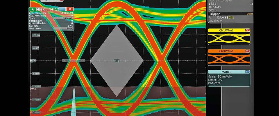
Not every problem needs a metal can. A ground plane beneath a sensitive trace already shields it from fields arriving from below, and a guard trace stitched to ground on both sides reduces coupling from an adjacent route. A can is reserved for the cases the planes cannot solve.
Where a can is used, its walls should touch ground at intervals that are a small fraction of the shortest wavelength of interest, and the reference plane underneath must be continuous. A can placed over a split plane provides almost no benefit.
Stackup as a Shield
A multilayer stackup provides shielding for free when it is arranged deliberately. Putting a solid ground plane next to the layer that carries the fastest signals keeps the field between the trace and the plane instead of letting it escape into the environment.
Ground planes on the outer layers also reduce the effect of external fields on the inner routing. The guidance is the same as for <a href="https://www.gopcba.com/emi-suppression-design-principles/” title=”EMI suppression”>EMI suppression in general: keep the return path continuous and the loop area small.
Radiation From Switching Circuits
Interference does not always arrive from outside. A switching regulator beside a sensitive receiver can be the dominant source, and the field it produces is broadband because the switching edges are fast. The layout of that circuit matters more than any can fitted later.
Loop area is the variable that counts. A tight input loop and a short return path reduce the field at the source, which is far cheaper than shielding the victim. The same techniques are described under radiated EMI layout.
Where Shielding Does Not Help
A shield cannot repair coupling that happens on the board itself, and it does not help when the disturbance travels on the ground or power network. If two traces are close enough to couple strongly, the cure is separation or a change of layer, not a cover.
Common-mode current is another case the shield does not block, because it flows on both conductors of a pair. It has to be controlled by balancing the pair and by managing the impedance of the path back to the source.
Selecting a Shield in Practice
The first question is the frequency of the disturbance. Below a few hundred megahertz the field behaves magnetically and a braid with low resistance carries the current; above that, a foil with full coverage is lighter and cheaper.
The second question is where the current returns. A shield is only as good as its termination, so a design that cannot provide a full circumferential bond should not expect the isolation a simulation predicts. Cable stiffness and cost decide the rest.
Additional Considerations for This Build
Practical attention to RFI pays for itself here, because it decides whether the finished board behaves as the drawing intended. Where the requirement is not stated on the fabrication drawing or in the assembly notes, the shop has to assume a default, and that default is rarely the value the design was simulated with. Stating RFI explicitly, together with the tolerance that applies, removes the assumption and keeps the result predictable from batch to batch.
Process Control and Verification
On a design of this kind, RFI is the item that decides how the rest of the board is arranged. Keeping a sample from the panel turns a dispute into a measurement, because the same coupon can be re-examined by both parties without rebuilding the batch. Reviewing the design before the data is released is cheaper than correcting it after the panel is in the tank, because every step downstream inherits the decision made at the front end.
Documenting the assumption is part of the design work, and a short note on the drawing prevents a question that would otherwise arrive a day later and cost a day of schedule.
A first article check confirms that the process and the drawing agree on the points listed above, and that the coupon data supports the values used in the design.
Where a measurement falls outside the expected window, the sample is retained so that the cause can be established before the balance of the batch is released.
FAQ
Does a shield have to be grounded? For electric fields it works while floating, but for magnetic fields and for radiated emissions it must be bonded to ground with a short, low impedance connection.
Is foil better than braid? Only at high frequency. Below a few hundred megahertz a braid has lower resistance and carries the induced shield current more effectively.
Can a shield fix board-level coupling? No. Coupling between traces on the same board is controlled by spacing, layer assignment and high frequency routing, not by an enclosure.